A signal modulation method and device
A signal modulation and signal technology, applied in the field of communication, can solve the problems of excess bandwidth, reduced spectral efficiency, anti-noise and attenuation ability of adverse signals, etc., to achieve the effect of improving the ability to resist noise and attenuation, and improving spectral efficiency
- Summary
- Abstract
- Description
- Claims
- Application Information
AI Technical Summary
Problems solved by technology
Method used
Image
Examples
Embodiment 1
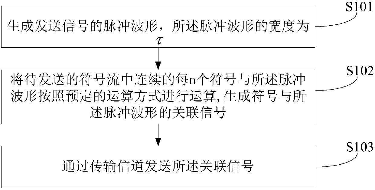
[0053] Figure 4 It shows the implementation process of the signal modulation method through the convolution operation model provided by the first embodiment of the present invention, and is described in detail as follows:
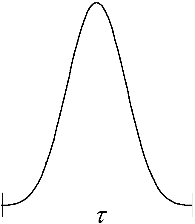
[0054] In step S401, the pulse waveform of the transmission signal is generated, the width of the pulse waveform is τ, wherein each pulse waveform is associated with n symbols (n>1), and the width of each symbol is Δτ,
[0055] The pulse waveform is as figure 2 shown.
[0056] In step S402, according to the convolution expression:
[0057] S i × h 0 +S i-1 × h 1 ...+S i-n+1 × h n-1 Obtain the associated signal generated between every n consecutive symbols in the symbol stream to be sent and the pulse waveform, wherein: the S i Represent the i-th symbol, and the h is a pulse waveform function, which can be expressed as h=[h 0 , h 1 ,...,h n-1 ], n represents the number of associated symbols, and each symbol is separated by Δτ.
[0058] The s...
Embodiment 2
[0063] Figure 7 It shows the implementation flow of the signal modulation method through the multiplication model provided by the second embodiment of the present invention, and is described in detail as follows:
[0064] In step S701, the pulse waveform of the transmission signal is generated, the width of the pulse waveform is τ, wherein each pulse waveform is associated with n symbols (n is an integer greater than 1), and the width of each symbol is Δτ,
[0065] In step S702, according to the multiplication expression: Obtaining an associated signal generated between every n consecutive symbols in the symbol stream to be sent and the pulse waveform, wherein: the S i Represent the i-th symbol, and the h is a pulse waveform function, which can be expressed as h=[h 0 , h 1 ,...,h n-1 ], each symbol is separated by Δτ.
[0066] Multiply the symbol stream S to be sent by the pulse waveform h. The model of the multiplication operation is as Figure 8 As shown, the proc...
Embodiment 3
[0070] Figure 9 A schematic structural diagram of the signal modulation device provided by the third embodiment of the present invention is shown, and the details are as follows:
[0071] The signal conditioning device described in the embodiment of the present invention includes:
[0072] The pulse waveform generation unit 901 is configured to generate the pulse waveform of the transmission signal, the width of the pulse waveform is τ, wherein each pulse waveform is associated with n symbols (n>1), and the width of each symbol is Δτ,
[0073] The computing unit 902 is configured to perform computation on each n consecutive symbols in the symbol stream to be sent and the pulse waveform according to a predetermined computing method, to generate a signal associated with the symbol and the pulse waveform;
[0074] The sending unit 903 is configured to send the associated signal through a transmission channel.
[0075] Preferably, the predetermined operation mode is convoluti...
PUM
 Abstract
Description
Claims
Application Information
 - R&D
- Intellectual Property
- Life Sciences
- Materials
- Tech Scout
- Unparalleled Data Quality
- Higher Quality Content
- 60% Fewer Hallucinations
Browse by: Latest US Patents, China's latest patents, Technical Efficacy Thesaurus, Application Domain, Technology Topic, Popular Technical Reports.
© 2025 PatSnap. All rights reserved.Legal|Privacy policy|Modern Slavery Act Transparency Statement|Sitemap|About US| Contact US: help@patsnap.com


