
Mechanical sealing device

A mechanical seal device and seal fit technology, which is applied in the direction of engine seals, mechanical equipment, engine components, etc., can solve problems such as seal failure and large rubber deformation, and achieve good sealing performance, long service life, and not easy to fail.

Inactive Publication Date: 2018-02-02
ZHEJIANG LUXI SEALS
View PDF8 Cites 3 Cited by
  • Summary
  • Abstract
  • Description
  • Claims
  • Application Information

AI Technical Summary

Problems solved by technology

[0007] The purpose of the present invention is to solve the problem of large deformation of rubber after being pressed, resulting in excessive extrusion and premature sealing failure, and to provide a rubber that can meet the requirements of high-pressure use on site, is not easy to fail, has good sealing performance, and has a long service life. mechanical seal

Method used


Image

  • Mechanical sealing device
  • Mechanical sealing device
  • Mechanical sealing device

Examples


Embodiment 1

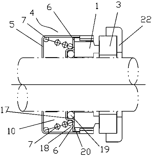
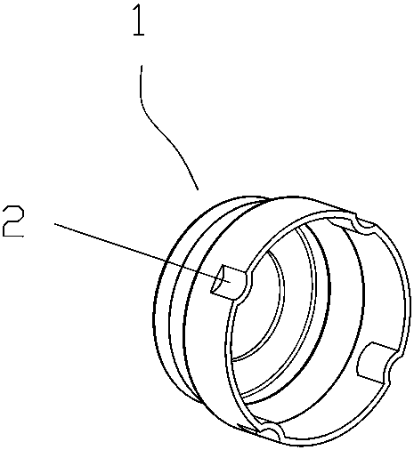
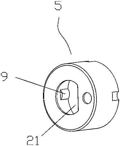
[0041] exist figure 1 , figure 2 , image 3 In the illustrated embodiment, a mechanical seal arrangement includes:

[0042] The moving ring 1 is a moving seal with sealing fit; a plurality of occlusal grooves 2 are evenly distributed on the ring surface of the moving ring 1;

[0043] The static ring 3 is a static seal that cooperates with the dynamic ring 1 to achieve sealing;

[0044]The elastic pushing component 4 is arranged on the outside of the moving ring 1 to drive the moving ring 1 to rotate and apply an axial thrust to the moving ring 1;

[0045] The elastic pushing assembly 4 includes a transmission seat 5, a push ring 6 and an elastic member 7. The push ring 6 is arranged inside the transmission seat 5 and connected with the end face of the moving ring 1, and the elastic member 7 is pressed between the transmission seat 5 and the push ring. between 6; the ring edge of the push ring 6 is evenly distributed with a plurality of occlusal arc grooves 8; the transmis...

Embodiment 2

[0053] exist Figure 6 , Figure 7 In the illustrated embodiment, a mechanical seal arrangement includes:

[0054] The moving ring 1 is a moving seal with sealing fit; a plurality of occlusal grooves 2 are evenly distributed on the annular surface of the moving ring 1;

[0055] The static ring 3 is a static seal that cooperates with the dynamic ring 1 to achieve sealing;

[0056] The elastic pushing component 4 is arranged on the outside of the moving ring 1 to drive the moving ring 1 to rotate and apply an axial thrust to the moving ring 1;

[0057] The elastic pushing assembly 4 includes a transmission seat 5, a push ring 6 and an elastic member 7. The push ring 6 is arranged inside the transmission seat 5 and connected with the end face of the moving ring 1, and the elastic member 7 is pressed between the transmission seat 5 and the push ring. between 6; the ring edge of the push ring 6 is evenly distributed with a plurality of occlusal arc grooves 8; the transmission se...

Embodiment 3

[0065] exist Figure 9 , Figure 10 , Figure 11 , Figure 14 In the illustrated embodiment, a mechanical seal arrangement includes:

[0066] The moving ring 1 is a moving seal with sealing fit; a plurality of occlusal grooves 2 are evenly distributed on the annular surface of the moving ring 1;

[0067] The static ring 3 is a static seal that cooperates with the dynamic ring 1 to achieve sealing;

[0068] The elastic pushing component 4 is arranged on the outside of the moving ring 1 to drive the moving ring 1 to rotate and apply an axial thrust to the moving ring 1;

[0069] The elastic pushing assembly 4 includes a transmission seat 5, a push ring 6 and an elastic member 7. The push ring 6 is arranged inside the transmission seat 5 and connected with the end face of the moving ring 1, and the elastic member 7 is pressed between the transmission seat 5 and the push ring. between 6; the ring edge of the push ring 6 is evenly distributed with a plurality of occlusal arc g...


PUM


Abstract

The invention discloses a mechanical sealing device. The mechanical sealing device comprises a moving ring, a stationary ring and an elastic pushing and pressing assembly, wherein the moving spring isthe sealed and matched moving sealing piece, and a plurality of engaged grooves are evenly distributed on the ring surface of the moving ring; the stationary ring is the stationary sealing piece which is matched and abutted against the moving ring to realize sealing; the elastic pushing and pressing assembly is arranged at the outer part of the moving ring to drive the moving ring to rotate and apply axial thrust to the moving ring; the elastic pushing and pressing assembly comprises a transmission seat, a pushing ring and an elastic pressing piece, the pursing ring is arranged inside the transmission seat and is connected with the end face of the moving ring in an abutting-against pressing mode, and the elastic pressing piece is arranged between the transmission seat and the pushing ring; a plurality of engaged arc grooves are evenly distributed on the ring edge of the pushing ring; and engaged protrusions which are engaged with the engaged grooves of the moving ring in a matched mode are arranged on the transmission seat. According to the mechanical sealing device, using requirements of high pressure on site can be met, efficacy losing is not easy to occur, sealing performance is good, and the service life is long.

Description

technical field [0001] The invention relates to the technical field of pumps, and more specifically relates to a mechanical sealing device. Background technique [0002] The rubber bellows mechanical seal currently used, the rubber bellows not only bears the pressure of the sealing chamber but also bears the transmission torque. In use, when the pressure is greater than 0.6MPa, the rubber will deform greatly after being pressed, resulting in excessive extrusion and premature seal failure. Therefore, it is necessary to carry out a new design of the sealing structure to meet the requirements of higher pressure on site. [0003] Chinese patent literature (announcement date: January 27, 2016, announcement number: CN 103352984B) discloses a rubber bellows mechanical seal structure for the pump shaft, which is installed between the pump casing and the pump shaft. Ring, moving ring, bellows, spring, spring seat, snap ring, stop pad, the outer end of the moving ring is coaxial with...

Claims


Application Information

Patent Timeline
Patent Type & Authority Applications(China)
IPC IPC(8): F16J15/34
CPCF16J15/3452F16J15/3464
Inventor 郭华
Owner ZHEJIANG LUXI SEALS
Learn More