Drilling hydraulic differential type density transducer steady-current bearing device
A density sensor and bearing device technology, applied in the field of oil and gas exploration, can solve problems such as increased exploration costs, unfavorable occupational health protection, and density measurement errors, so as to reduce the probability of downhole accidents, benefit occupational health protection, and eliminate density measurement errors Effect
- Summary
- Abstract
- Description
- Claims
- Application Information
AI Technical Summary
Problems solved by technology
Method used
Image
Examples
Embodiment 1
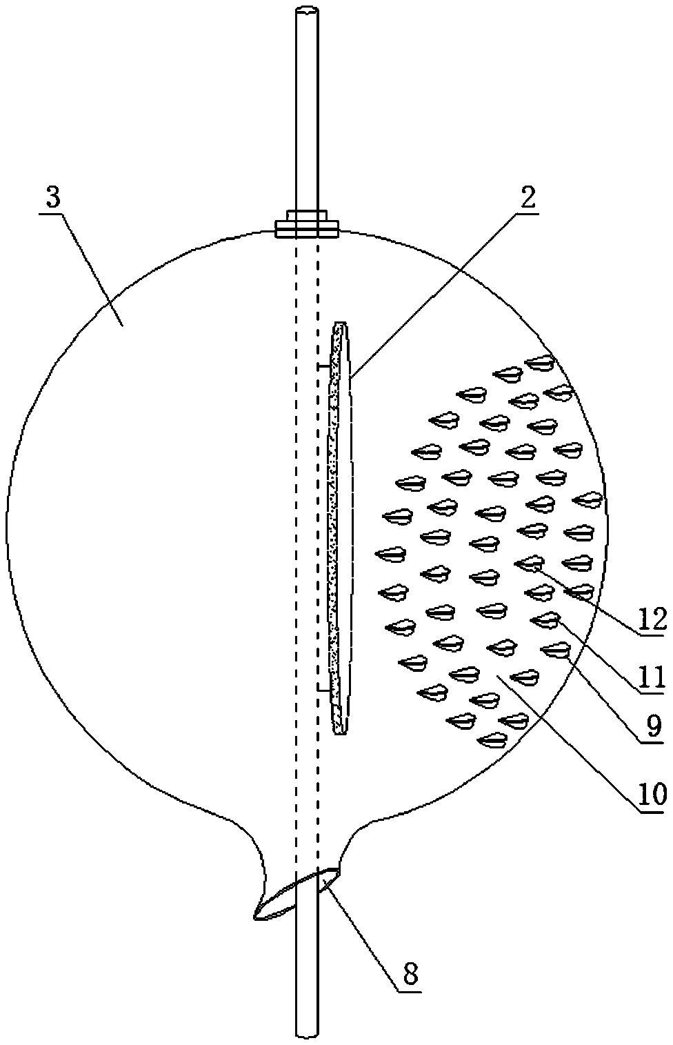
[0067] As shown in the figure, the structure of the steady flow bearing device of the differential density sensor for drilling hydraulic pressure of the present invention includes a sensor support rod 1 and a sensor pressure diaphragm 2. The sensor pressure diaphragm 2 is arranged on the rod of the sensor support rod 1. The pressure diaphragm 2 is fixedly connected to the rod body of the sensor support rod 1 through a bracket,
[0068] A ball cover 3 is provided on the periphery of the sensor support rod 1 where the sensor pressure diaphragm 2 is located;
[0069] The spherical cover 3 is formed by buckling two parts of the front flow surface hemispherical cover 4 and the back flow surface hemispherical cover 5 through the cover flange 14.
[0070] The convex spherical crown of the front flow dome cover 4 faces the left side of the sensor rod 1,
[0071] The convex spherical crown of the dorsal hemispherical cover 5 faces the right side of the sensor rod 1,
[0072] The front flow surf...
Embodiment 2
[0085] The steady flow bearing device of the drilling hydraulic differential density sensor. Its structure includes a sensor support rod and a sensor pressure diaphragm. The sensor pressure diaphragm is arranged on the rod of the sensor support rod. The sensor pressure diaphragm 2 is fixedly connected to the sensor support rod 1 through a bracket. On the shaft,
[0086] An integral spherical cover is provided on the periphery of the sensor support rod where the sensor pressure diaphragm is located;
[0087] The left half of the integrated dome cover is the front flow surface, and the right half of the integrated dome cover is the back flow dome cover.
[0088] The convex spherical crown of the front surface faces the left side of the sensor rod,
[0089] The convex spherical crown of the back flow surface faces the right side of the sensor rod,
[0090] The front flow surface and the back flow surface enclose the sensor support rod section containing the sensor pressure diaphragm in th...
PUM
| Property | Measurement | Unit |
|---|---|---|
| density | aaaaa | aaaaa |
| diameter | aaaaa | aaaaa |
| thickness | aaaaa | aaaaa |
Abstract
Description
Claims
Application Information
 - R&D Engineer
- R&D Manager
- IP Professional
- Industry Leading Data Capabilities
- Powerful AI technology
- Patent DNA Extraction
Browse by: Latest US Patents, China's latest patents, Technical Efficacy Thesaurus, Application Domain, Technology Topic, Popular Technical Reports.
© 2024 PatSnap. All rights reserved.Legal|Privacy policy|Modern Slavery Act Transparency Statement|Sitemap|About US| Contact US: help@patsnap.com


