
Module testing equipment and testing method

A technology of module testing and equipment, which is applied in the direction of testing optical performance, etc., and can solve the problem of low efficiency of module testing

Pending Publication Date: 2018-01-30
NINGBO SUNNY INSTR
View PDF10 Cites 4 Cited by
  • Summary
  • Abstract
  • Description
  • Claims
  • Application Information

AI Technical Summary

Problems solved by technology

[0003] The purpose of the present invention is to provide a module testing equipment and testing method to solve the problem of low efficiency of module testing

Method used


Image

  • Module testing equipment and testing method
  • Module testing equipment and testing method
  • Module testing equipment and testing method

Examples


Embodiment approach

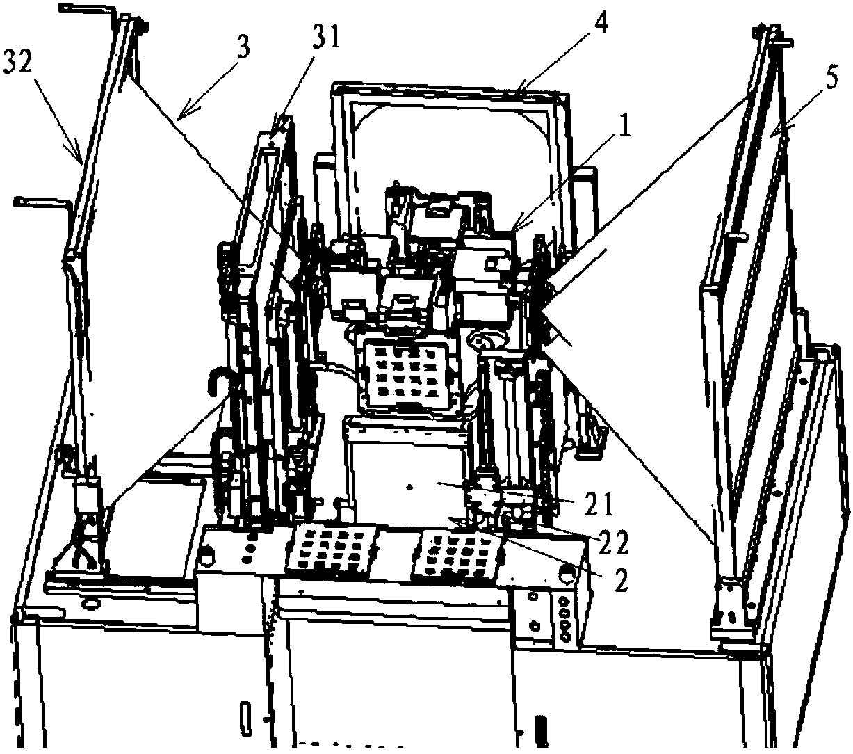
[0121] combine figure 2 and Figure 5As shown, according to an embodiment of the present invention, the near-focus testing module 31 includes a near-focus light source 311 , a near-focus target plate 312 , a first near-focus driving mechanism 313 , a second near-focus driving mechanism 314 , and a near-focus support 315 . In this embodiment, the near-focus light source 311 is supported on the near-focus bracket 315 , and the near-focus light source 311 can move relative to the near-focus bracket 315 along the vertical direction. The near-focus target plate 312 is detachably installed on the near-focus light source 311 , and the near-focus target plate 312 on the near-focus light source 311 can be easily replaced according to test requirements. The first near-focus driving mechanism 313 is connected with the near-focus light source 311, and the near-focus light source 311 can move up and down in the vertical direction by driving the first near-focus driving mechanism 313, and...


PUM


Abstract

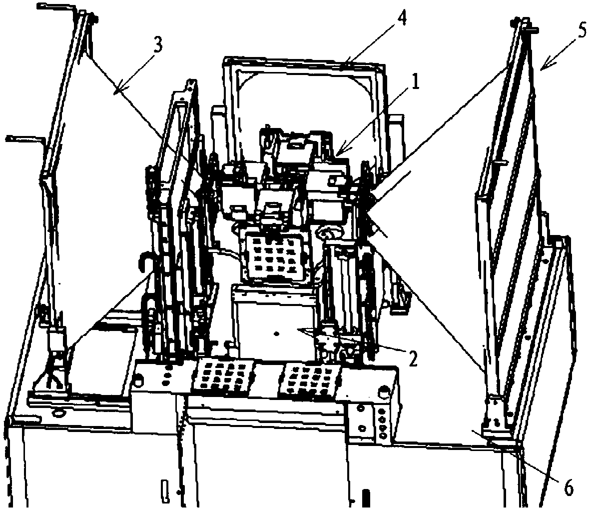
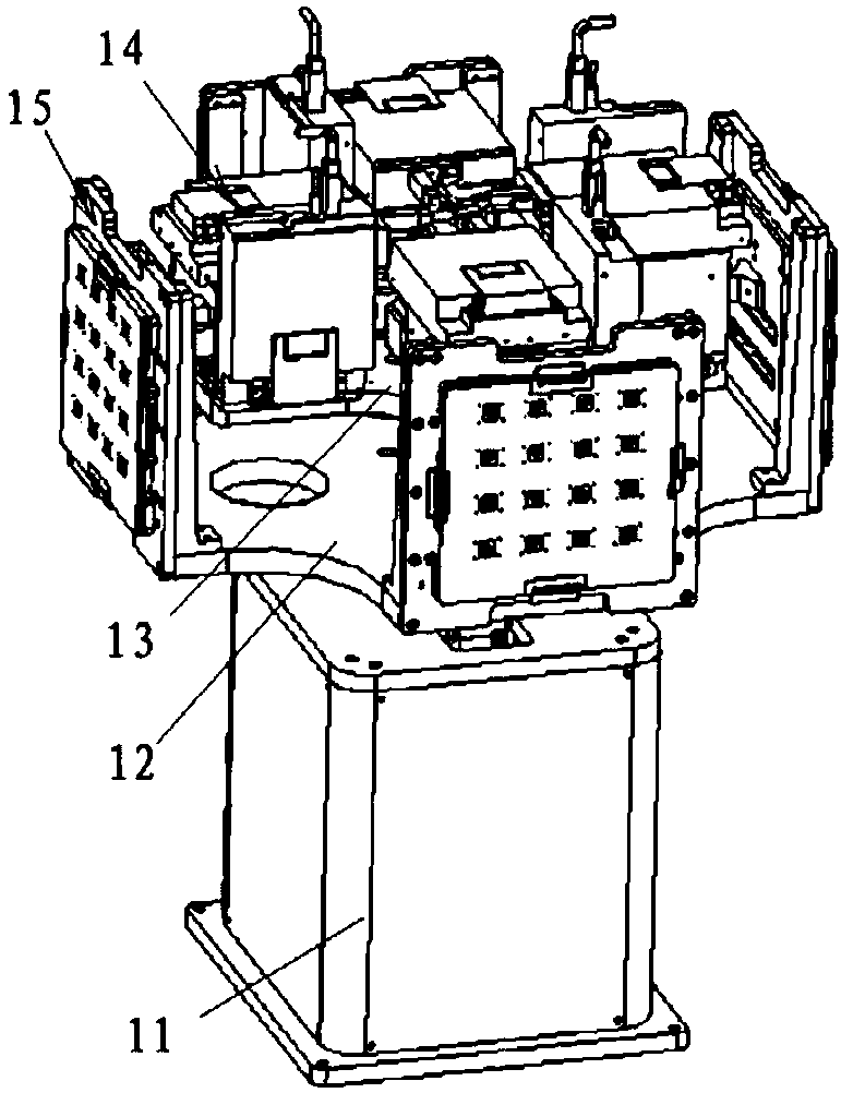
The invention relates to module testing equipment and a module testing method. The module testing equipment comprises a clamping unit, a first testing unit, a second testing unit, a third testing unitand a fourth testing unit, wherein the clamping unit is arranged in a manner of mutually moving and opposite to the first test unit, the second test unit, the third test unit and the fourth test unit. The different testing units are evenly distributed around the clamping unit, so that the structure of the module testing equipment is compact, the different testing units can be centrally arranged in the same equipment, the effect of completing different testing items in the same equipment can be realized, the testing efficiency of a module is effectively improved, and the occupied area of the equipment is reduced; and the different testing units are arranged in a manner of surrounding the clamping unit, thus the testing efficiency of the module testing equipment is further improved.

Description

technical field [0001] The invention relates to a test device and a test method, in particular to a module test device and a test method. Background technique [0002] At present, with the rapid development of the camera module industry, the requirements for the product quality of the camera module are further increased. Correspondingly, the test items for the camera module increase accordingly. Existing testing equipment can only test a single item of the camera module, and the detection efficiency is low, which seriously affects the production efficiency of the camera module. At the same time, the camera module is switched between multiple test equipment, resulting in inconsistent detection standards, which in turn affects the test accuracy of the product. Due to the single test items of the existing test equipment, it is necessary to purchase different equipment to complete the inspection of the camera module, resulting in high cost and poor compatibility, which affects...

Claims


Application Information

Patent Timeline
Patent Type & Authority Applications(China)
IPC IPC(8): G01M11/02
Inventor 柯海挺梁敬姣陈冠余张宝忠
Owner NINGBO SUNNY INSTR
Learn More