
Water conservancy equipment with injection molding function

A technology of injection molding and water conservancy, which is applied in the direction of water conservancy engineering equipment, water conservancy engineering, forming conveyors, etc. It can solve the problems of affecting the quality of injection molding, high labor intensity of operation, and excessive addition of materials, so as to improve the quality of injection molding and reduce labor costs. The effect of simple input and device structure

Inactive Publication Date: 2018-01-30
CIXI QICHENG MACHINERY TECH CO LTD
View PDF6 Cites 2 Cited by
  • Summary
  • Abstract
  • Description
  • Claims
  • Application Information

AI Technical Summary

Problems solved by technology

[0002] In the construction of water conservancy infrastructure, it is often necessary to use the injection mold to inject the mixed concrete raw materials such as (cement abutment, cement column), etc. However, the traditional injection molding operation is done manually, and the operation is labor-intensive and the work efficiency is relatively low. , there are many automatic molding devices in the existing market, but their use costs are relatively high, and at the same time, they cannot meet the quantitative feeding operation according to the size of the mold, which makes it very easy to add too much material and the phenomenon that the mold is full, resulting in Great waste while affecting the quality of injection molding

Method used


Image

  • Water conservancy equipment with injection molding function
  • Water conservancy equipment with injection molding function
  • Water conservancy equipment with injection molding function

Examples


Embodiment Construction

[0019] All features disclosed in this specification, or steps in all methods or processes disclosed, may be combined in any manner, except for mutually exclusive features and / or steps.

[0020] Any feature disclosed in this specification (including any appended claims, abstract and drawings), unless expressly stated otherwise, may be replaced by alternative features which are equivalent or serve a similar purpose. That is, unless expressly stated otherwise, each feature is one example only of a series of equivalent or similar features.

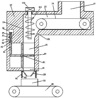
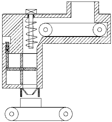
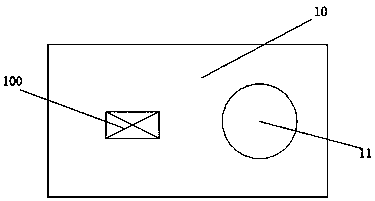
[0021] Such as Figure 1-3 As shown, a water conservancy equipment that can be injection molded according to the present invention includes a frame body 10, the upper end of the frame body 10 is fixedly installed with a port 11 connected to the stirring device, and the frame body 10 is provided with a transfer groove 12. The first transfer machine 31 is installed in the transfer tank 12, and the vertically extending drain tank 13 is arranged ...


PUM


Abstract

The invention discloses water conservancy equipment with an injection molding function. The water conservancy equipment comprises a frame; a port connected with stirring equipment is fixedly installedin the upper end of the frame; a conveying trough is formed in the frame, and a first conveyor is installed in the conveying trough; a discharging trough extending in the vertical direction is formedin the frame; a rotating cavity is further formed in the frame, a discharging outlet is formed in the bottom wall of the rotating cavity, and a rotating rack is rotationally installed in the rotatingcavity and comprises a rotating shaft rotationally installed in the front and rear end walls of the rotating cavity and rotating plates uniformly and fixedly installed on the rotating shaft; a telescopic trough is formed in the left end wall of the frame; a guide trough extending in the vertical direction is formed in the top wall of the rotating cavity, a through trough is formed in the bottom wall of the guide trough, a guide block is installed in the guide trough in a vertically sliding mode, and a touch rod is fixedly installed at the lower end of the guide block and penetrates through the through trough to penetrate into the rotating cavity. The water conservancy equipment is simple in structure and low in equipment cost.

Description

technical field [0001] The invention relates to the technical field of water conservancy, in particular to a water conservancy equipment capable of injection molding. Background technique [0002] In the construction of water conservancy infrastructure, it is often necessary to use the injection mold to inject the mixed concrete raw materials such as (cement abutment, cement column), etc. However, the traditional injection molding operation is done manually, and the operation is labor-intensive and the work efficiency is relatively low. , there are many automatic molding devices in the existing market, but their use costs are relatively high, and at the same time, they cannot meet the quantitative feeding operation according to the size of the mold, which makes it very easy to add too much material and the phenomenon that the mold is full, resulting in It is a great waste and affects the quality of injection molding. Contents of the invention [0003] The object of the pr...

Claims


Application Information

Patent Timeline
IPC IPC(8): B28B5/02B28B13/02E02B1/00
Inventor 葛国松何华勇
Owner CIXI QICHENG MACHINERY TECH CO LTD
Learn More