
Wind farm voltage control method by combining energy storage

A voltage control method and voltage control technology, applied in wind power generation, reactive power compensation, reactive power adjustment/elimination/compensation, etc., can solve the problem of ignoring the reactive power adjustment capability of wind turbines, prone to voltage oscillation, and large number of wind turbines, etc. question

Inactive Publication Date: 2018-01-26
锐电科技有限公司
View PDF13 Cites 5 Cited by
  • Summary
  • Abstract
  • Description
  • Claims
  • Application Information

AI Technical Summary

Problems solved by technology

[0003] The wind turbines in the wind farm can realize decoupling control of active power and reactive power. Although the reactive power adjustment range of a single unit is small, there are many fans in large wind farms, and the reactive power adjustment capability of wind turbines is basically ignored in actual operation. Causes waste of reactive power of wind turbines
[0004] At present, in order to solve the problem of reactive power and voltage control at the grid-connected point of the wind farm and improve the response speed of the reactive power adjustment of the wind farm, reactive power compensation equipment is installed in the wind farm. However, multiple reactive power compensation devices lack coordination ability, and the adjustment is easy There is a voltage shock

Method used


Image

  • Wind farm voltage control method by combining energy storage
  • Wind farm voltage control method by combining energy storage
  • Wind farm voltage control method by combining energy storage

Examples


Embodiment Construction

[0030] The following will clearly and completely describe the technical solutions in the embodiments of the present invention with reference to the accompanying drawings in the embodiments of the present invention. Obviously, the described embodiments are only some, not all, embodiments of the present invention. Based on the embodiments of the present invention, all other embodiments obtained by persons of ordinary skill in the art without making creative efforts belong to the protection scope of the present invention.

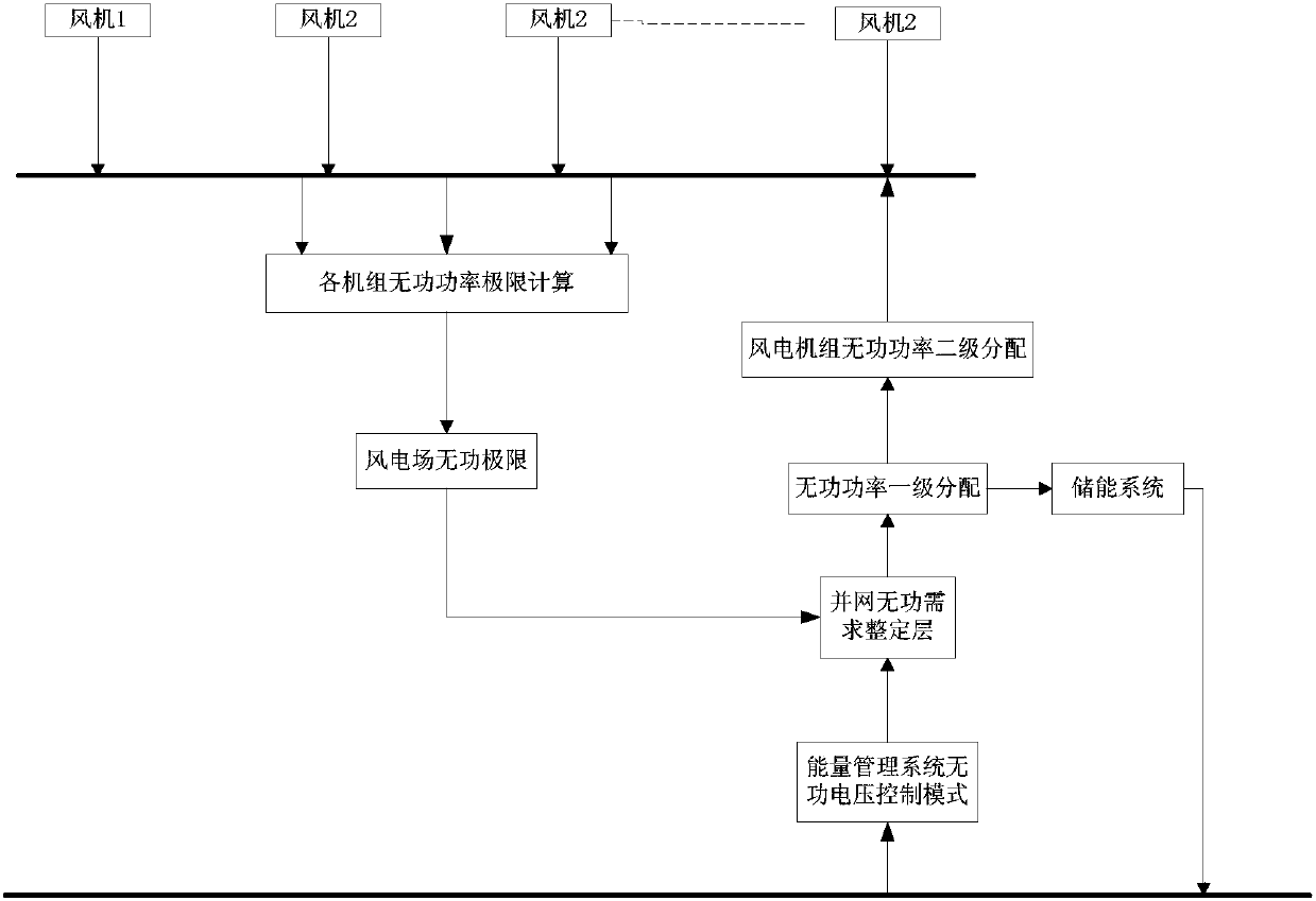
[0031] The invention takes the voltage of the grid-connected point of the wind farm as the control target, takes the reactive power as the adjustment amount, and makes the voltage of the grid-connected point meet the voltage requirement of the grid through the coordinated control of the wind turbine and the energy storage equipment.

[0032] Such as figure 1 As shown, it is a schematic diagram of reactive power and voltage control of a wind farm including ener...


PUM


Abstract

The invention discloses a wind farm voltage control method by combining energy storage. The method comprises the following steps of (S1) measuring an actual voltage value of a grid connection point ofa wind farm and calculating deviation between a target voltage value of the grid connection point and the actual voltage value; (S2) setting a dead zone threshold of the voltage deviation, if the voltage deviation is greater than the dead zone threshold, entering the step (S3), or else, returning to the step (S1); (S3) calculating a reactive power instruction value of the wind farm; (S4) calculating a maximum value and a minimum value of reactive power of a single unit, participating in reactive voltage control, in the wind farm and calculating the maximum values and the minimum values of thereactive power of all units, participating in reactive voltage control, in the wind farm; and (S5) carrying out coordination distribution on the reactive power instruction value of the wind farm between a wind generator unit and energy storage equipment according to the principle of preferentially adjusting the reactive power of the energy storage equipment and then adjusting the reactive power of the wind generator unit.

Description

technical field [0001] The invention belongs to the field of reactive voltage control of wind farms, in particular to a reactive voltage control technology including energy storage equipment. Background technique [0002] The operation of large-scale wind power connected to the grid has a great impact on the dispatching and control of the grid. In addition, the wind power grid-connected guidelines of various countries put forward strict requirements for grid-connected wind farms. For example, it is required that grid-connected wind farms should have high-precision wireless The power and voltage adjustment capability, and the reactive power of the wind farm should be able to automatically adjust within its capacity range. [0003] The wind turbines in the wind farm can realize decoupling control of active power and reactive power. Although the reactive power adjustment range of a single unit is small, there are many fans in large wind farms, and the reactive power adjustment ...

Claims


Application Information

Patent Timeline
Patent Type & Authority Applications(China)
IPC IPC(8): H02J3/38H02J3/50H02J3/18
CPCY02E10/76Y02E40/30
Inventor 甘家飞华青松朴金姬李飞飞刘克昌
Owner 锐电科技有限公司
Learn More