Display structure, method and electronic device
A technology for displaying structure and light, applied in instruments, nonlinear optics, optics, etc., can solve the problems of large thickness, affecting the aesthetics of electronic equipment, and high cost of anti-peeping film
- Summary
- Abstract
- Description
- Claims
- Application Information
AI Technical Summary
Problems solved by technology
Method used
Image
Examples
Embodiment 1
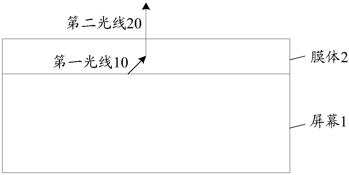
[0032] An embodiment of the present invention provides a display structure, the composition of the display structure, such as figure 1 As shown, including screen 1 and film body 2;
[0033] In an optional embodiment, the screen 1 is configured to project the first light 10 generated by itself to the film body 2 at a first angle.
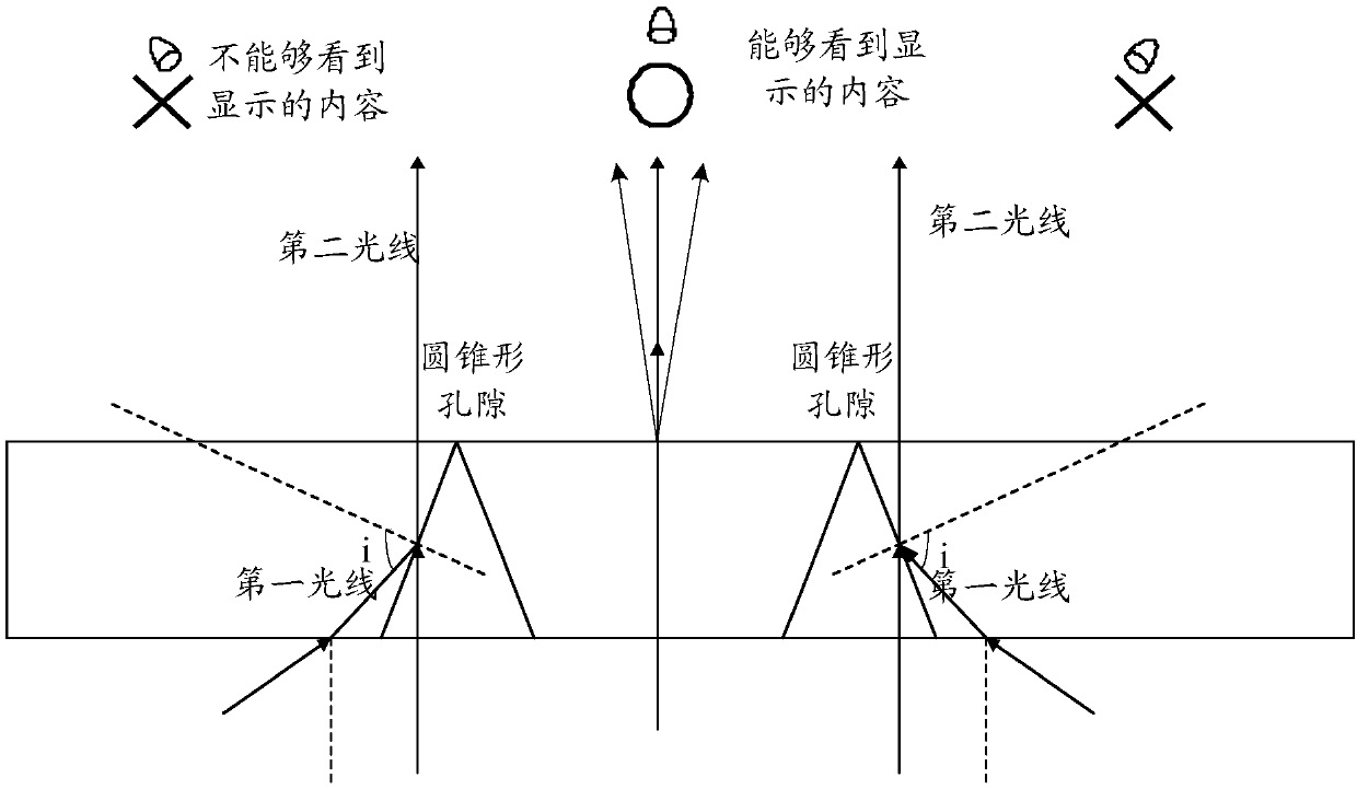
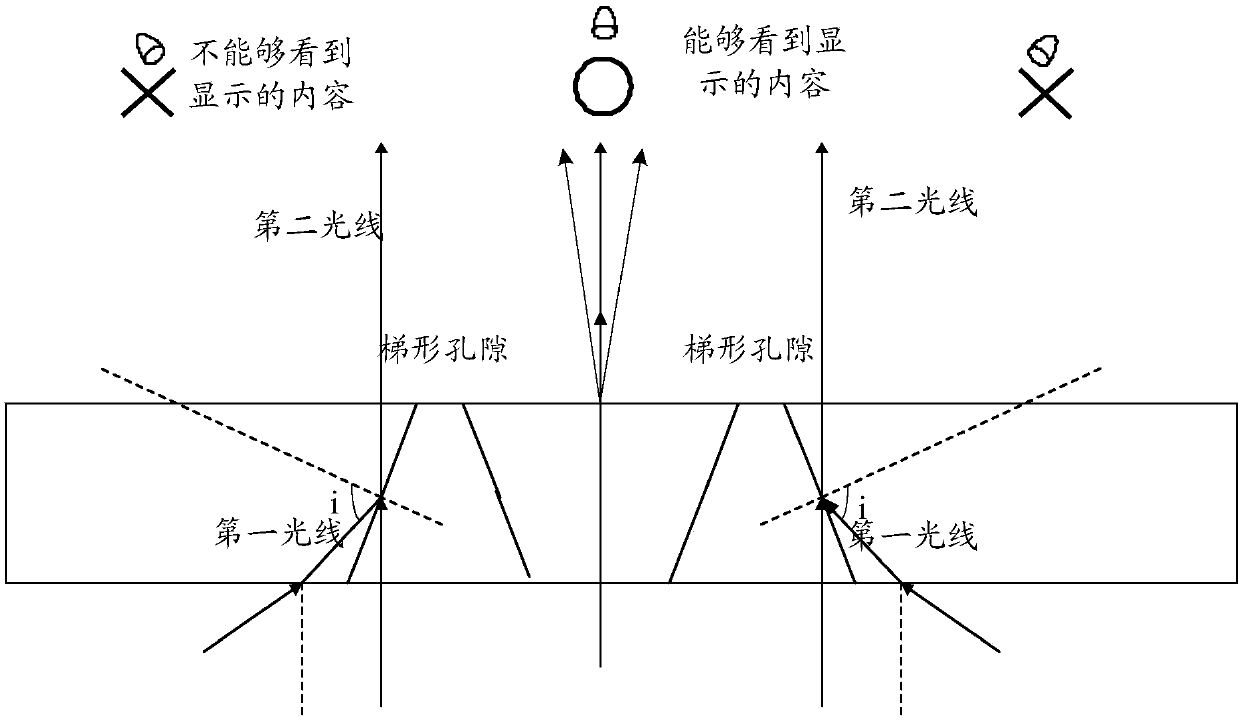
[0034] Here, the first light 10 can be generated by the light source (such as a backlight) of the screen itself, and the first angle is within the preset incident angle threshold range; the preset angle threshold means that the light is projected to the film body, inside the film body 2 The angle at which total reflection can occur.
[0035] The film body 2 is used for receiving a first light 10 incident at a first angle and projecting a second light 20 at a second angle.
[0036] Here, the amount of light of the second light 20 is the same as that of the first light 10, and the first angle is different from the second angle; wherein, the differenc...
Embodiment 2
[0052] Based on the above Figure 1 to Figure 5 As shown in the screen and film body, Embodiment 2 of the present invention provides a display structure, and a schematic diagram of another optional composition structure of the display structure, as shown in Figure 6 As shown, including screen 1 and film body 2; where,
[0053] The screen 1 is configured to project the first light 10 generated by itself to the film body 2 at a first angle.
[0054] Here, the first angle is within a preset threshold angle of incidence; the preset angle threshold refers to an angle at which light rays are projected onto the film body and total reflection can occur inside the film body.
[0055] The screen 1 at least includes: a color filter substrate 11 and a polarizer 12 ; the size of the film body 2 is smaller than or equal to the size of the polarizer 12 . Here, the size refers to the area, that is, the area of the film body 2 is smaller than or equal to the area of the polarizer 12 . ...
Embodiment 3
[0068] Based on the above Figure 1 to Figure 5 As shown in the screen and film body, Embodiment 3 of the present invention provides a display structure, and a schematic diagram of another optional composition structure of the display structure, as shown in Figure 7 As shown, including screen 1 and film body 2; where,
[0069] The screen 1 is configured to project the first light 10 generated by itself to the film body 2 at a first angle.
[0070] Here, the first angle is within a preset threshold angle of incidence; the preset angle threshold refers to an angle at which light rays are projected onto the film body and total reflection can occur inside the film body.
[0071] The screen 1 at least includes: a color filter substrate 11 and a polarizer 12 ; the size of the film body 2 is smaller than or equal to the size of the polarizer 12 . Here, the size refers to the area, that is, the area of the film body 2 is smaller than or equal to the area of the polarizer 12 . ...
PUM
| Property | Measurement | Unit |
|---|---|---|
| refractive index | aaaaa | aaaaa |
Abstract
Description
Claims
Application Information
 - R&D
- Intellectual Property
- Life Sciences
- Materials
- Tech Scout
- Unparalleled Data Quality
- Higher Quality Content
- 60% Fewer Hallucinations
Browse by: Latest US Patents, China's latest patents, Technical Efficacy Thesaurus, Application Domain, Technology Topic, Popular Technical Reports.
© 2025 PatSnap. All rights reserved.Legal|Privacy policy|Modern Slavery Act Transparency Statement|Sitemap|About US| Contact US: help@patsnap.com


