
Workpiece clamping mechanism

A clamping mechanism and workpiece technology, applied in metal processing machinery parts, clamping, manufacturing tools, etc., can solve problems such as easy failure to meet design requirements and inaccurate workpiece positioning.

Inactive Publication Date: 2018-01-26
TONGLING HUIYU IND CO LTD
View PDF6 Cites 5 Cited by
  • Summary
  • Abstract
  • Description
  • Claims
  • Application Information

AI Technical Summary

Problems solved by technology

[0002] The clamping mechanism is a mechanism to clamp the workpiece. Because some workpieces have high requirements or need to be processed, only clamping can be used. The existing clamping mechanism is under the action of external force. Although it is not easy to move, it is easy to rotate along the hole or groove, resulting in inaccurate positioning of the workpiece, and it is easy to fail to meet the design requirements when processing the workpiece

Method used


Image

  • Workpiece clamping mechanism
  • Workpiece clamping mechanism
  • Workpiece clamping mechanism

Examples


Embodiment 1

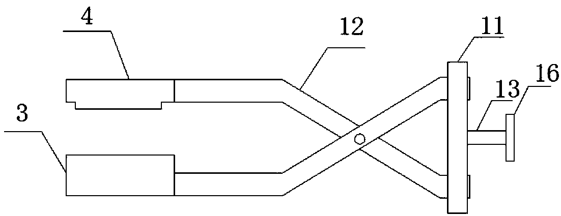
[0018] Such as Figure 1-7 , a workpiece clamping mechanism of the present invention includes a lower limit block 3 and an upper limit block 4, a clamp rod 12 runs through the bottom end of the lower limit block 3 and extends to the inside of the lower limit block 3, and passes through the lower limit block 3 and the upper limit block 4. The setting of the upper limit block 4 is conducive to moving up and down, so as to clamp the workpiece and prevent it from sliding during work. A connecting plate 11 is arranged on one side of the clamping rod 12, and through the connection of the connecting plate 11, there is It is beneficial to connect two clamping rods 12 to prevent the clamping rods 12 from being damaged during long-term work. Both ends of the connecting plate 11 are provided with clamping rods 12, and the two clamping rods 12 are movably connected by a rotating shaft. One end of the clamping rod 12 runs through the connecting plate 11 and extends to one side of the conne...

Embodiment 2

[0023] Such as Figure 1-7 , a workpiece clamping mechanism of the present invention is used in the clamping device of the condenser core, including a lower clamping shell 1 and an upper clamping shell 2, the upper clamping shell 2 is arranged on the top of the lower clamping shell 1, the lower clamping shell 1 The top of the clamp shell 1 is provided with a lower limit block 3, the bottom end of the upper clamp shell 2 runs through the lower limit block 3, and extends to the inside of the lower limit block 3, and the bottom end of the lower clamp shell 1 is provided with an upper limit block 4, through The setting of the lower limit block 3 and the upper limit block 4 is conducive to moving up and down, so as to realize the clamping of the condenser core up and down to prevent it from sliding during operation. Limiting block 5, the inner wall of one side of the upper clamping shell 2 is provided with a right limiting block 6, through the setting of the left limiting block 5 a...


PUM


Abstract

The invention discloses a workpiece clamping mechanism which comprises a lower limiting block and an upper limiting block; a first clamping bar penetrates through the bottom end of the lower limitingblock and extends to the interior of the lower limiting block; a connecting plate is arranged on one side of the first clamping bar; the first clamping bar and a second clamping bar are arranged on the identical sides of the two ends of the connecting plate; the two clamping bars are movably connected through a rotary shaft; one end of the second clamping bar penetrates through the connecting plate and extends to one side of the connecting plate; one end of the first clamping bar and one end of the second clamping bar are movably connected with the connecting plate; one end of the second clamping bar on one side is connected with one end of the upper limiting block; a screw rod is arranged on one side of the connecting plate; one end of the screw rod penetrates through the connecting plateand extends to the interior of the connecting plate; and a second rotary cap is arranged at one end of the screw rod. With the adoption of the lower limiting block and the upper limiting block, up-and-down motion is facilitated, so that a workpiece can be clamped vertically, and is prevented from sliding during working, and the purpose of the workpiece clamping mechanism is achieved.

Description

technical field [0001] The invention relates to the field of clamping technology, in particular to a workpiece clamping device. Background technique [0002] The clamping mechanism is a mechanism for clamping the workpiece. Because some workpieces have high requirements or need to be processed, only clamping can be used. The existing clamping mechanism is under the action of external force. Although it is not easy to move, it is easy to rotate along the hole or groove, resulting in inaccurate positioning of the workpiece, and it is easy to fail to meet the design requirements when processing the workpiece. [0003] Therefore, it is necessary to invent a work clamping device with good fixability to solve the above problems. Contents of the invention [0004] The purpose of the present invention is to provide a workpiece clamping mechanism to solve the problems raised in the background art above. [0005] In order to achieve the above object, the present invention provides...

Claims


Application Information

Patent Timeline
Patent Type & Authority Applications(China)
IPC IPC(8): B23Q3/06
Inventor 周飞吴伦保王焘徐善龙汤明明邹文冬吴光辉
Owner TONGLING HUIYU IND CO LTD
Learn More