Automotive solid-state relay with NMOS tube and over-current protection
A solid-state relay and overcurrent protection circuit technology, applied in electrical components, electronic switches, pulse technology, etc., can solve problems such as hindering the popularization and use of solid-state relays, high cost, and complex circuit redundancy.
- Summary
- Abstract
- Description
- Claims
- Application Information
AI Technical Summary
Problems solved by technology
Method used
Image
Examples
Embodiment Construction
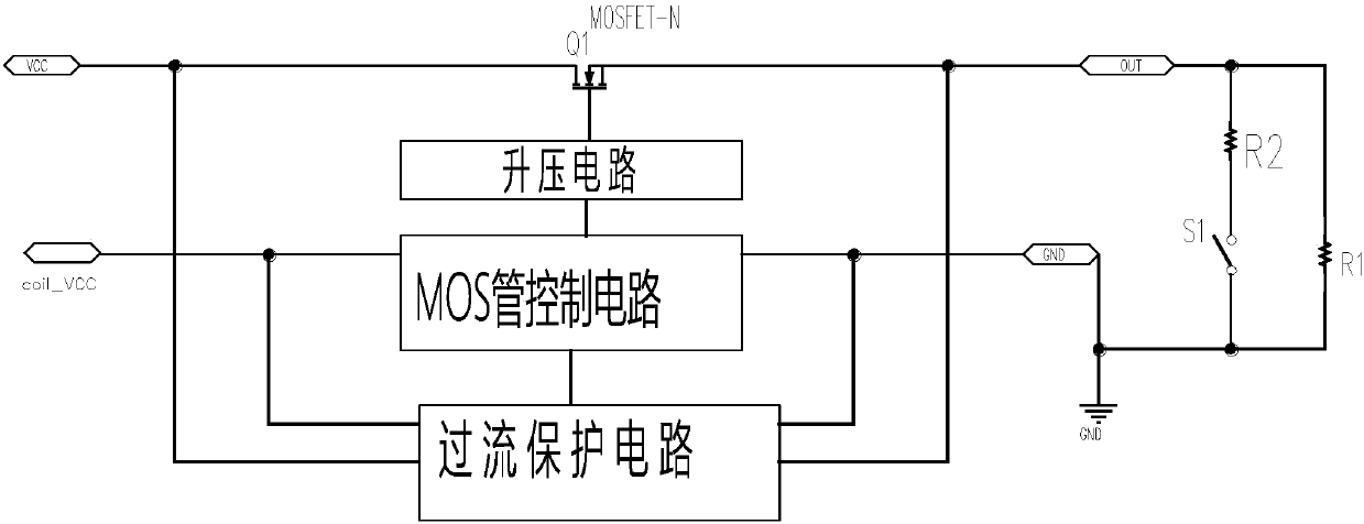
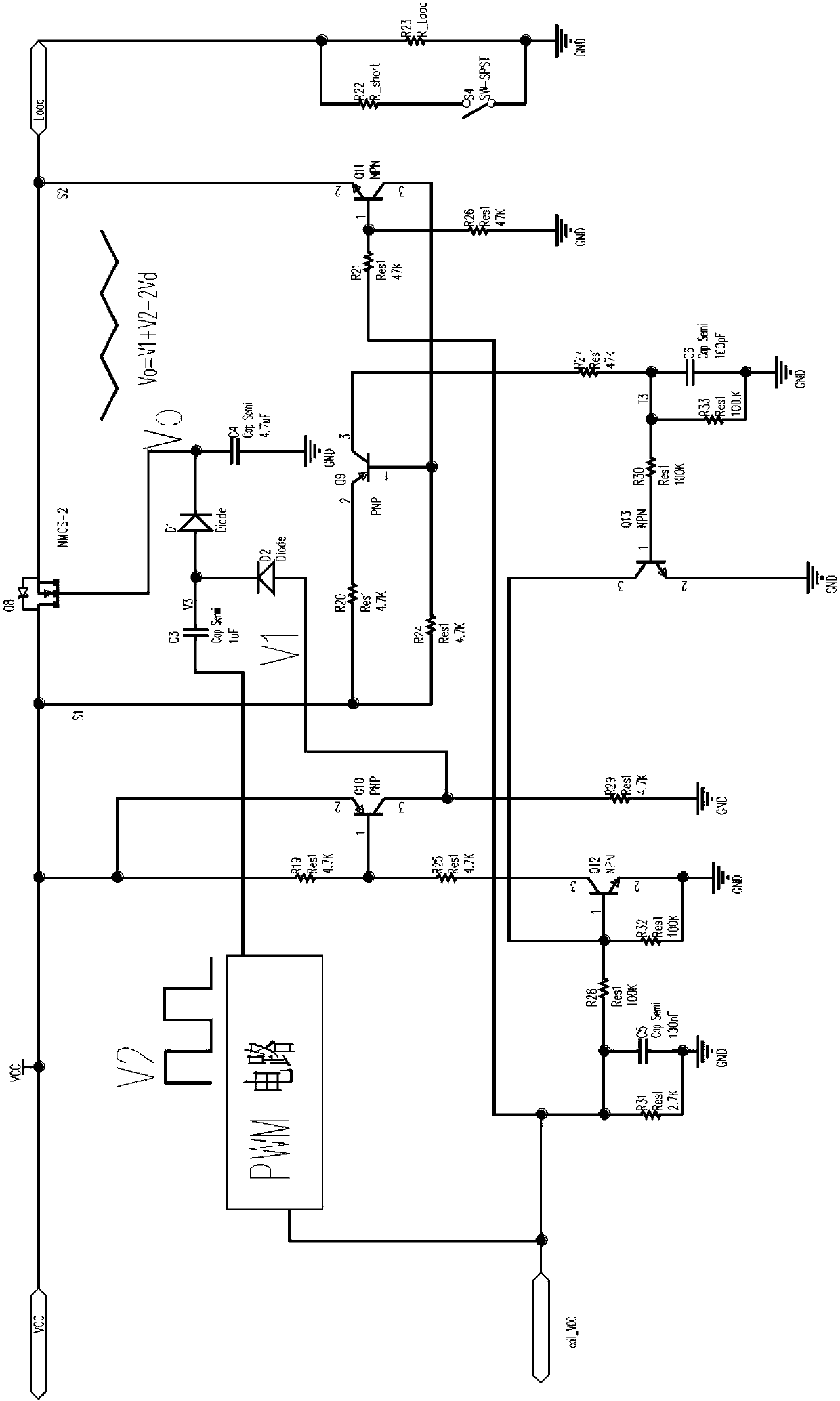
[0021] Such as figure 1 As shown, since N-channel MOS transistors are usually only suitable for low-side drive, a boost circuit is required if high-side drive is required. When the coil_VCC (solid state relay control terminal power supply) is powered on, the MOS tube control circuit is driven to work through the boost circuit to turn on the MOS tube Q1 and output normally.
[0022] When the switch S1 is turned on, the output load increases instantly, and the MOS tube is in the overcurrent stage. The overcurrent protection circuit uses the RDS of the MOS tube itself (the on-resistance of the MOS tube, usually several milliohms to hundreds of milliohms) in the case of overcurrent voltage drop, when the current reaches a certain threshold, the trigger protection circuit turns off the MOS The tube control circuit turns off the MOS tube to realize the overcurrent protection of the MOS tube Q1. This switch S1 is used to simulate an overcurrent situation. The conduction of S1 can b...
PUM
 Abstract
Description
Claims
Application Information
 - R&D Engineer
- R&D Manager
- IP Professional
- Industry Leading Data Capabilities
- Powerful AI technology
- Patent DNA Extraction
Browse by: Latest US Patents, China's latest patents, Technical Efficacy Thesaurus, Application Domain, Technology Topic, Popular Technical Reports.
© 2024 PatSnap. All rights reserved.Legal|Privacy policy|Modern Slavery Act Transparency Statement|Sitemap|About US| Contact US: help@patsnap.com


