
Special radiator fan structure for microelectronic equipment

A heat dissipation fan and heat dissipation fan technology, applied to mechanical equipment, parts of pumping devices for elastic fluids, non-variable pumps, etc., can solve the problems of complex installation, easy to burn equipment, large volume, etc., and achieve faster The efficiency of heat dissipation, effective and uniform heat transfer, and the effect of increasing the heat dissipation area

Active Publication Date: 2018-01-23
ANHUI UNIVERSITY OF TECHNOLOGY AND SCIENCE
View PDF6 Cites 0 Cited by
  • Summary
  • Abstract
  • Description
  • Claims
  • Application Information

AI Technical Summary

Problems solved by technology

The theoretical basis of its development is modern physics established from the end of the 19th century to the 1930s. Microelectronics technology includes a series of specialized technologies such as system circuit design, device physics, process technology, material preparation, automatic testing, packaging, and assembly. , Microelectronics technology is the sum of various process technologies in microelectronics. Due to the small size and high power operation of microelectronic equipment, it generates very high heat, and excessive heat will easily reduce the operating efficiency of microelectronic equipment such as chips. At the same time, it is easy to burn the equipment, which is very important for the heat dissipation of microelectronic equipment. At this stage, most of them use heat sinks for heat dissipation, but the heat dissipation effect is poor. The cost of good heat dissipation radiators is too high, the volume is large, and the installation is complicated

Method used


Image

  • Special radiator fan structure for microelectronic equipment
  • Special radiator fan structure for microelectronic equipment
  • Special radiator fan structure for microelectronic equipment

Examples


Embodiment

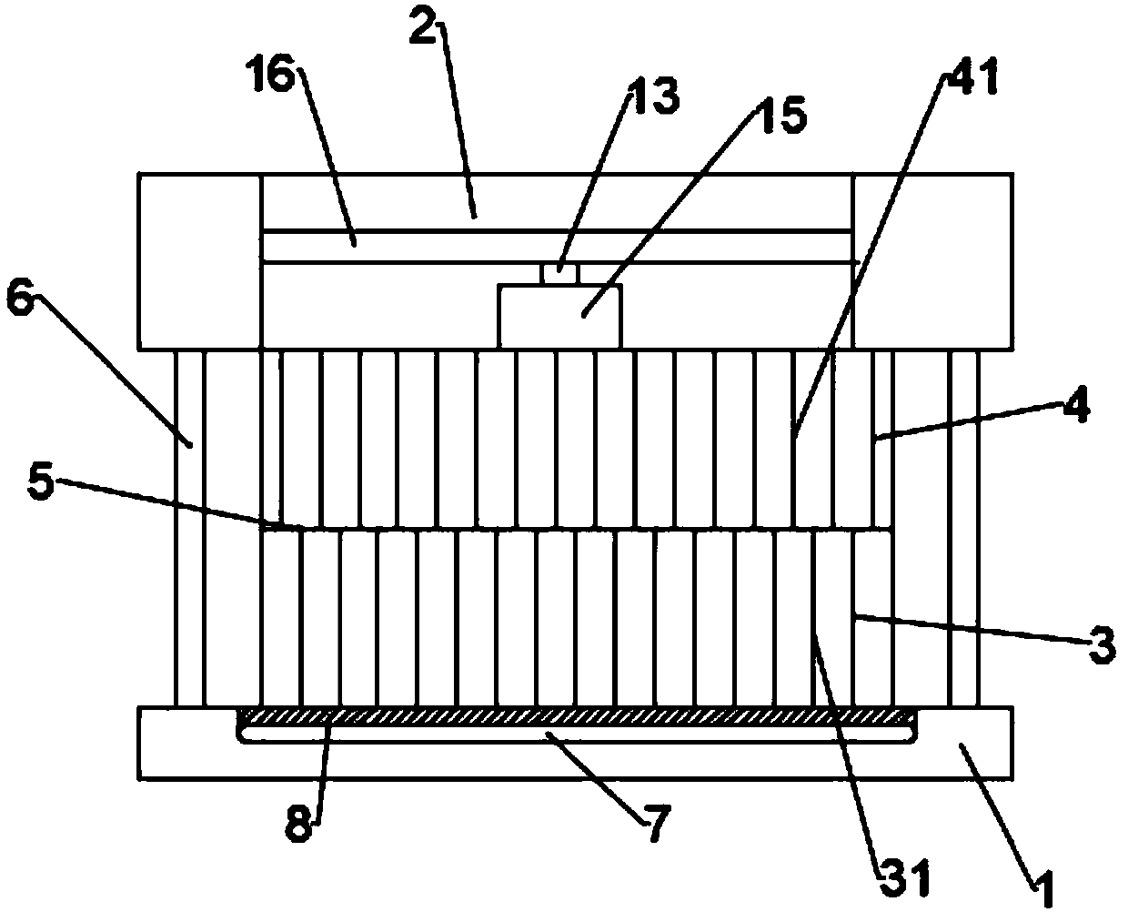
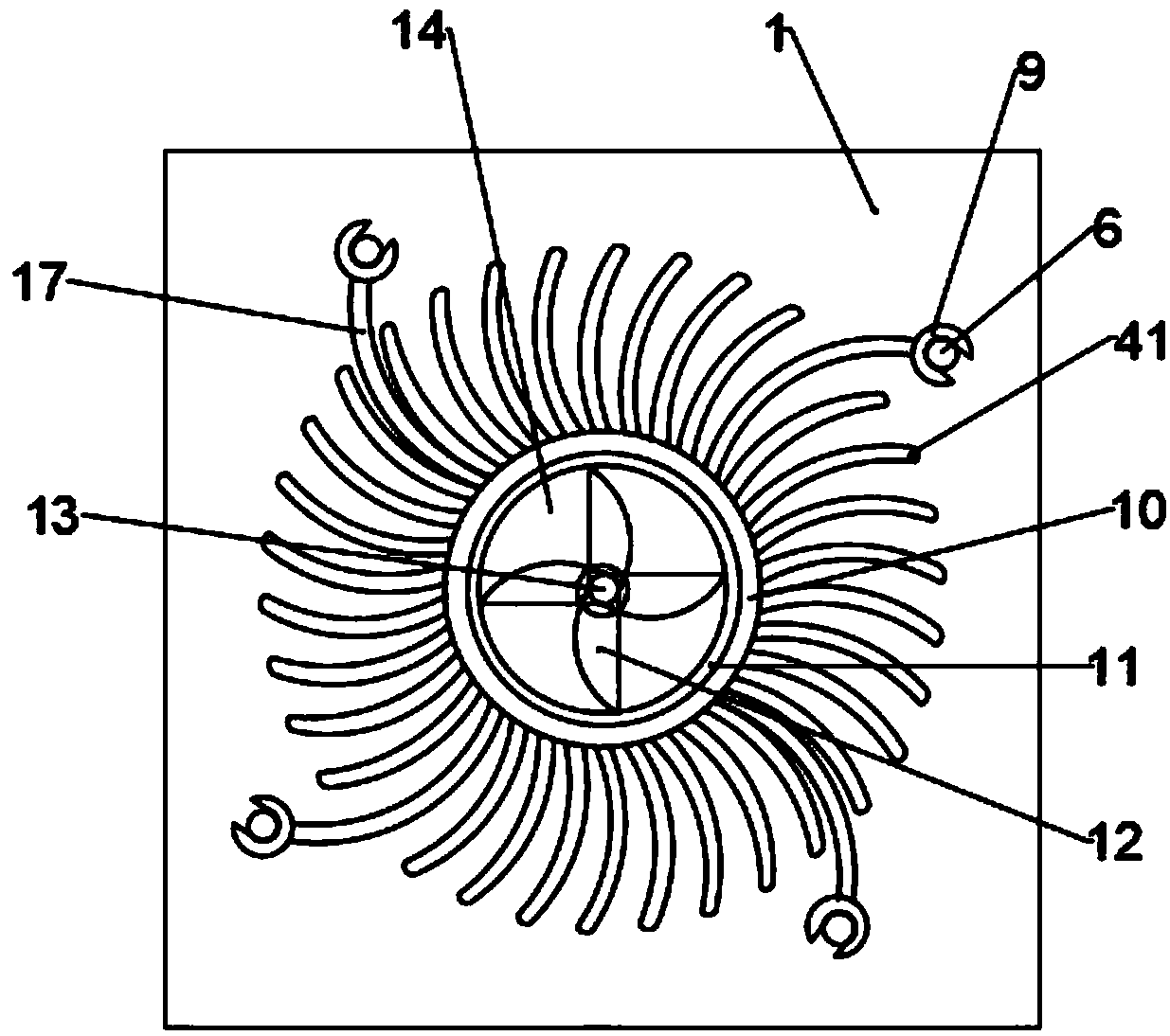
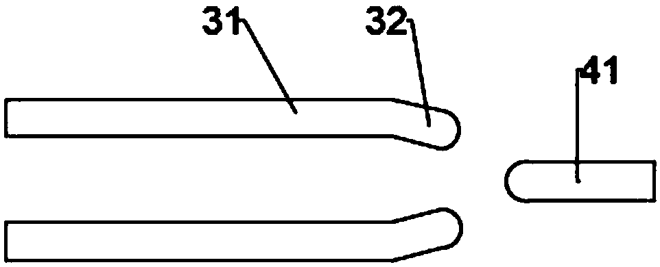
[0020] Such as figure 1 , figure 2 , image 3 and Figure 4 As shown, the present invention provides a special cooling fan structure for microelectronic equipment, including a bottom connecting plate 1, a fan 2, a first cooling fan 3 and a second cooling fan 4, and the bottom connecting plate 1 is installed on the first cooling fan 3 bottom, the first heat dissipation fan 3 and the second heat dissipation fan 4 are fixedly connected together, and the connection between the first heat dissipation fan 3 and the second heat dissipation fan 4 is provided with a flow gap 5, and the fan 2 is installed on the second On the top of the heat dissipation fan 4, a conduction ring 10 is arranged in the middle of the first heat dissipation fan 3 and the second heat dissipation fan 4, and the inner contact ring 11 is set inside the conduction ring 10, and the surface of the inner contact ring 11 is uniformly provided with Radiation sheet 111, and the radiation sheet 111 is embedded in th...


PUM


Abstract

The invention discloses a special radiator fan structure for microelectronic equipment. The special radiator fan structure comprises a bottom connecting plate, a fan, a first radiator fan and a secondradiator fan, wherein the bottom connecting plate is mounted at the bottom of the first radiator fan; the first radiator fan and the second radiator fan are fixedly connected together; a flow exchange gap is formed at the joint of the first radiator fan and the second radiator fan; the fan is mounted at the top of the second radiator fan; a conduction ring is arranged in the middle of each of thefirst radiator fan and the second radiator fan; each conduction ring sleeves an inner connecting ring; radiation pieces are uniformly arranged on the surface of each inner connecting ring and embedded into rectangular grooves of the corresponding conduction ring; an impeller is mounted in the middle of the interior of each conduction ring; the impellers are driven by a rotating shaft to rotate; adriving motor is connected to the top of the rotating shaft; the rotating shaft penetrates the driving motor and is connected with fan blades; and the driving motor and the fan blades are arranged inthe fan. Owing to the multi-layer fan structure, multi-stage progressive air intake and exhaust in the structure are realized; and meanwhile, the heat dissipation area is increased through arc-shapedfins, and the heat dissipation efficiency is improved.

Description

technical field [0001] The invention relates to the technical field of microelectronic equipment, in particular to a cooling fan structure dedicated to microelectronic equipment. Background technique [0002] Microelectronics technology is a new technology developed along with integrated circuits, especially VLSIs. The theoretical basis of its development is modern physics established from the end of the 19th century to the 1930s. Microelectronics technology includes a series of specialized technologies such as system circuit design, device physics, process technology, material preparation, automatic testing, packaging, and assembly. , Microelectronics technology is the sum of various process technologies in microelectronics. Due to the small size and high power operation of microelectronic equipment, it generates very high heat, and excessive heat will easily reduce the operating efficiency of microelectronic equipment such as chips. , At the same time, it is easy to burn ...

Claims


Application Information

Patent Timeline
Patent Type & Authority Applications(China)
IPC IPC(8): F04D25/08F04D25/16F04D29/58
Inventor 李臣龙
Owner ANHUI UNIVERSITY OF TECHNOLOGY AND SCIENCE
Learn More