


Quick Research
Generate reliable direction feasibility study reports for your R&D in just a few steps.

Technical Q&A
Discover and master advanced knowledge NOW. Basics, ideas, possibilities, all at once.

Find Solutions
As an expert in R&D theories, this can generate solutions to your technical problems instantly.

Evaluate Feasibility
Analyze your overall solution with one click, know your potential R&D risks in advance.

Monitor Landscape
Get weekly tech updates, stay abreast of the latest tech innovations and key insights.
Bearing box on European type crane
A crane and bearing box technology, applied in the field of European crane wheels, can solve the problems of short service life, low bearing capacity, outdated wheel design, etc., and achieve the effects of saving production costs, reducing maintenance costs, and reducing overall height
- Summary
- Abstract
- Description
- Claims
- Application Information
AI Technical Summary
Problems solved by technology
Method used
Image

Examples
Embodiment Construction
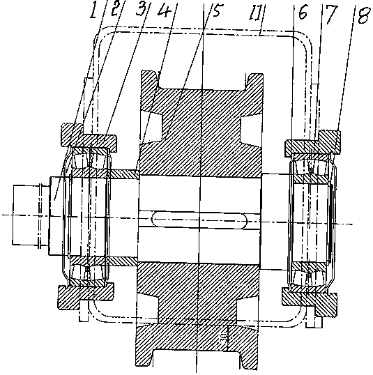
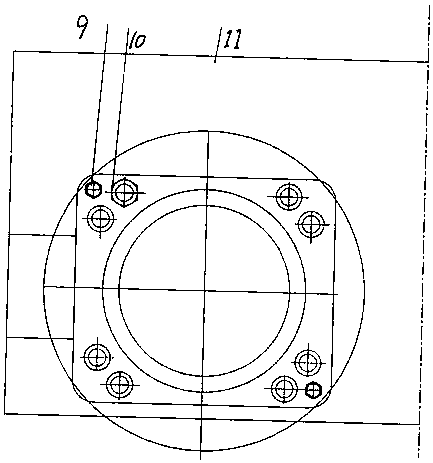
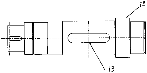
[0008] Embodiments are described in detail in conjunction with the above accompanying drawings, as Figure 1-Figure 4 As shown, the end beam 11 is made of a cold-formed rectangular tube, which not only reduces the weld seam, but also has high strength and aesthetic appearance, and the driving wheel axle 1 is stepped (such as image 3 ), the step 12 at one end is fixed with a self-aligning roller bearing 7, and the other end is fixed with a spacer sleeve 4. The end of the driving wheel shaft connected to the reducer is made into a flat key or splines, the outer shape of the bearing chamber 3 is square, and the spherical roller bearing is assembled in the bearing chamber and cannot be moved by its inner convex edge. Further, from figure 1 The cross-section of the marked bearing chamber 3 shows that the bearing chamber is an inverted Z shape. The purpose of this setting is that when the spherical roller bearing needs to be replaced, only the bearing chamber needs to be removed, a...
PUM
 Abstract
Description
Claims
Application Information
 - R&D Engineer
- R&D Manager
- IP Professional
- Industry Leading Data Capabilities
- Powerful AI technology
- Patent DNA Extraction
Browse by: Latest US Patents, China's latest patents, Technical Efficacy Thesaurus, Application Domain, Technology Topic, Popular Technical Reports.
© 2024 PatSnap. All rights reserved.Legal|Privacy policy|Modern Slavery Act Transparency Statement|Sitemap|About US| Contact US: help@patsnap.com