
Mechanical locking device for crusher rotary shaft

A crusher and mechanical lock technology, applied in grain processing and other directions, can solve the problem that the rotating shaft cannot be locked, and achieve the effect of high hardness, toughness and high mechanical strength

Pending Publication Date: 2018-01-23
SID MACHINERY BEIJING
View PDF16 Cites 0 Cited by
  • Summary
  • Abstract
  • Description
  • Claims
  • Application Information

AI Technical Summary

Problems solved by technology

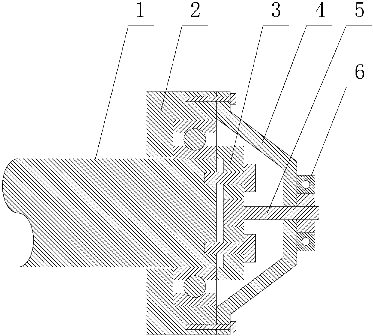
[0004] The purpose of the present invention is to provide a mechanical locking device for the rotating shaft of a crusher to solve the problem that the rotating shaft of the existing crusher cannot be locked

Method used


Image

  • Mechanical locking device for crusher rotary shaft
  • Mechanical locking device for crusher rotary shaft
  • Mechanical locking device for crusher rotary shaft

Examples


Embodiment Construction

[0026] The technical solutions of the present invention will be clearly and completely described below in conjunction with the accompanying drawings. Apparently, the described embodiments are some of the embodiments of the present invention, but not all of them. Based on the embodiments of the present invention, all other embodiments obtained by persons of ordinary skill in the art without making creative efforts belong to the protection scope of the present invention.

[0027] In the description of the present invention, it should be noted that the terms "center", "upper", "lower", "left", "right", "vertical", "horizontal", "inner", "outer" etc. The indicated orientation or positional relationship is based on the orientation or positional relationship shown in the drawings, and is only for the convenience of describing the present invention and simplifying the description, rather than indicating or implying that the referred device or element must have a specific orientation, ...


PUM


Abstract

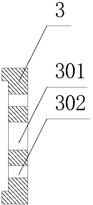
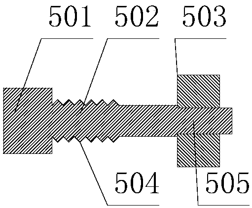
The invention relates to the technical field of crushing equipment, in particular to a mechanical locking device for a crusher rotary shaft. The mechanical locking device comprises a bearing pressingcover, a lock pin, a bearing seat and a locking blanking cover. The bearing pressing cover is mounted on the rotary shaft, the rotary shaft is mounted in the bearing seat, and a flat key pin hole is formed in the bearing pressing cover. The lock pin comprises a flat key pin, a connecting rod and a limiting block, the connecting rod is connected with the flat key pin and the limiting block, and theflay key pin is arranged in the flat key pin hole. The locking blanking cover is mounted on the bearing seat, a penetrating hole is formed in the locking blanking cover, and the connecting rod penetrates through the penetrating hole. A limiting mechanism is arranged on the locking blanking cover, a limiting hole is formed in the limiting mechanism, and the limiting block is located in the limiting hole. According to the mechanical locking device for the crusher rotary shaft, the problem that a rotary shaft of an existing crusher cannot be locked is solved.

Description

technical field [0001] The invention relates to the technical field of crushing equipment, in particular to a mechanical locking device for a rotating shaft of a crusher. Background technique [0002] In many industries, crushers are used to crush and recycle waste materials. In the daily application process, the transportation and maintenance of crushers are often involved. The existing crushers are not equipped with mechanical locking devices, which causes the main shaft to break during transportation. Rotation, or when overhauling equipment, mishandling may cause the spindle to rotate. [0003] The crushing knife in the crusher is sharp and strong, and the rotation of the main shaft during transportation or maintenance may damage the internal structure of the crusher or cause personal injury. Therefore, it is urgent to develop a mechanical locking device, which can selectively lock the main shaft of the crusher according to the working conditions, so that the main shaft ...

Claims


Application Information

Patent Timeline
IPC IPC(8): B02C18/14B02C18/24B02C18/16
Inventor 多纳特·伯施皮尔让·夏尔诺
Owner SID MACHINERY BEIJING
Learn More