Slideable lifting appliance

A spreader and sliding technology, which is applied in the direction of load hanging components, hoisting equipment braking devices, bottom support structures, etc., can solve the problems of short sliding distance, short sliding stroke of oil cylinder and oil cylinder, frequent maintenance of steel wire rope, etc., to achieve Avoid maintenance, increase distance, and slide easily and flexibly

Pending Publication Date: 2018-01-19
SUZHOU DAFANG SPECIAL VEHICLE
View PDF5 Cites 0 Cited by
  • Summary
  • Abstract
  • Description
  • Claims
  • Application Information

AI Technical Summary

Problems solved by technology

The power for the slippage of the spreader is usually pulled by the hoisting wire rope, which has the disadvantages of complex structure and frequent maintenance of the wire rope; even if it is pushed and pulled by the oil cylinder, the oil cylinder is also arranged on the beam of the gantry crane. Above, due to the limitation of space, the length of the cylinder is limited so that the stroke of the cylinder is very short, resulting in a very short sliding distance

Method used


Image

  • Slideable lifting appliance
  • Slideable lifting appliance

Examples


Embodiment Construction

[0024] The present invention will be further described below in conjunction with accompanying drawing and embodiment:

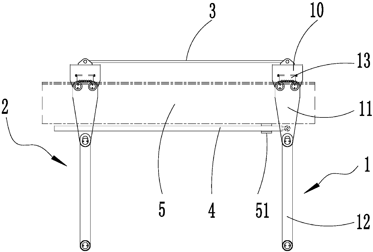
[0025] As shown in the figure, a slidable spreader includes an active spreader 1, a driven spreader 2 connected with the active spreader 1, and a power component for driving the active spreader 1 to slide. Active spreader 1 and driven spreader 2 are connected through connecting rod 3 .

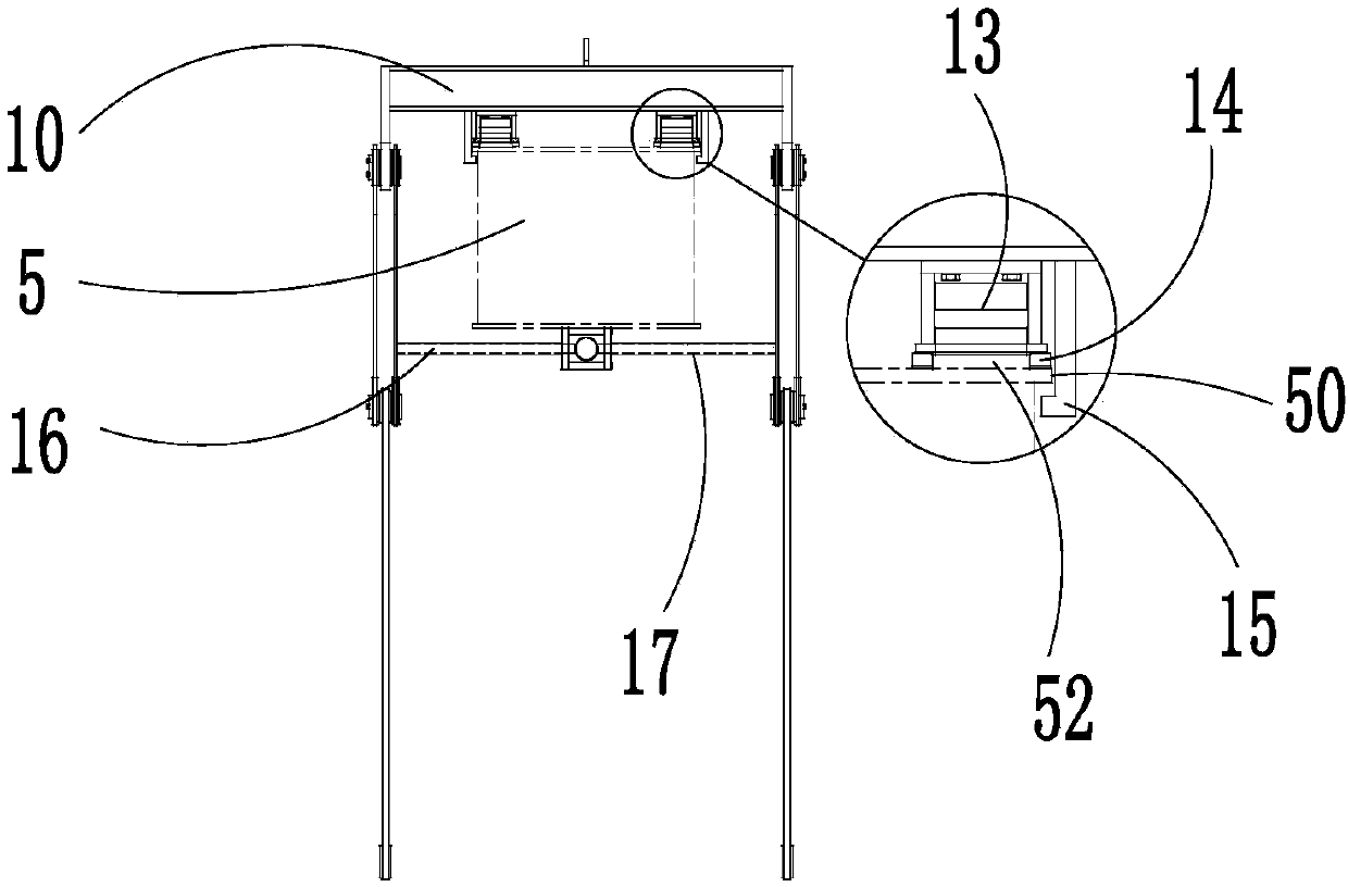
[0026] In this embodiment: the active spreader 1 includes a fixed frame 10, a suspension plate assembly connected to the fixed frame 10, and a rolling assembly connected to the bottom of the fixed frame 10. The lower part of the rolling assembly and the upper part of the power part are formed for the beam to pass through. space, that is to say: when the slidable spreader is installed on the beam 5, the rolling assembly is arranged above the beam 5, and the power part is located below the beam 5.

[0027] There are two sets of hanging plate assemblies, and the two sets of han...


PUM


Abstract

The invention relates to a slideable lifting appliance. The slideable lifting appliance comprises a driving lifting appliance body, a driven lifting appliance body connected with the driving lifting appliance body, and a power unit used for driving the driving lifting appliance body to slide. The driving lifting appliance body comprises fixed frames, hanger plate assemblies connected to the corresponding fixed frames, and rolling assemblies connected to the bottoms of the corresponding fixed frames. A space allowing a cross beam of a portal crane to penetrate through is formed below the rolling assemblies and above the power unit. The lifting appliance can be moved and adjusted on the cross beam. The power unit is arranged below the cross beam, so that the slippage distance is greatly increased. By adoption of rolling friction between the rolling assemblies and the cross beam, slippage is made more portable and flexible. The trouble of repair and maintenance in the pulling mode of a hoisting steel wire rope is avoided.

Description

technical field [0001] The invention relates to a special spreader used in the fields of construction, power manufacturing, large-scale installation, transportation and the like, in particular to a slidable spreader. Background technique [0002] Spreaders are usually used for hoisting heavy objects in hoisting machinery, such as gantry cranes (gantry cranes), etc. At present, most of the gantry cranes on the market are wheel-rail type. The track is pre-laid when in use, and the spreader set on the gantry crane is usually fixed. When it is necessary to lift heavy objects: the gantry crane moves through the track to align the spreader with the heavy object. The lifting is completed, but because the track is relatively fixed, once the position of the heavy object cannot be aligned by moving on the track, it will cause difficulty in lifting. [0003] Therefore, there are movable spreaders on the market. Similar spreaders on the existing market generally adopt static friction ...

Claims


Application Information

Patent Timeline
Patent Type & Authority Applications(China)
IPC IPC(8): B66C5/04B66C9/14
Inventor 刘继英高爱华
Owner SUZHOU DAFANG SPECIAL VEHICLE
Why Eureka
Try Eureka