
Carbon fiber composite subway vehicle body formed through low cost process

A composite material and carbon fiber technology, used in railway car body, railway car body parts, transportation and packaging, etc., can solve the problems of short service cycle, poor corrosion resistance, high energy consumption, etc., to reduce the number of parts and heat insulation. Excellent performance and the effect of improving safety performance

Inactive Publication Date: 2018-01-19
HENGSHEN
View PDF0 Cites 7 Cited by
  • Summary
  • Abstract
  • Description
  • Claims
  • Application Information

AI Technical Summary

Problems solved by technology

[0005] The purpose of the present invention is to provide a carbon fiber composite subway car body formed by a low-cost process. The subway car body is designed as a carbon fiber composite material structure. Combined with the characteristics of the composite material forming process, the components are integrated to give full play to the potential of the composite material. Strong design, high degree of integration, good fatigue performance and other advantages, in order to reduce the structural weight of the car body while improving the characteristics of fatigue, sound insulation and heat insulation of the car body. In addition, the main part of the car body uses low-cost non-hot pressing The tank process (OOA) molding greatly reduces the cost of the carbon fiber composite car body, and solves the existing problems of the original aluminum alloy car body in the prior art, such as heavy weight, high cost, large energy consumption, poor corrosion resistance, and short service life.

Method used


Image

  • Carbon fiber composite subway vehicle body formed through low cost process
  • Carbon fiber composite subway vehicle body formed through low cost process
  • Carbon fiber composite subway vehicle body formed through low cost process

Examples


Embodiment

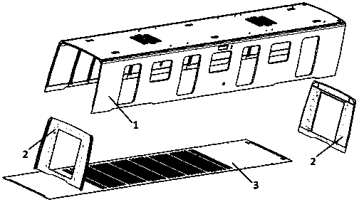
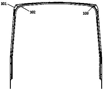
[0037] A carbon fiber composite subway car body formed by a low-cost process, such as figure 1 , including a U-shaped body 1, an end wall 2 and an underframe 3, the U-shaped body 1 is arranged on the underframe 3, the common ends of the U-shaped body 1 and the underframe 3 are respectively provided with an end wall 2, and the U-shaped body 1 adopts Sandwich structure, such as image 3 , the U-shaped body 1 includes an outer skin 101, a sandwich layer 103 and an inner skin 102 arranged sequentially from outside to inside, such as Figure 5 , the end wall 2 adopts a sandwich structure, and the end wall 2 includes an outer skin 201, a sandwich layer 203, and an inner skin 202 arranged sequentially from outside to inside, such as Figure 7 , the underframe 3 adopts a sandwich structure, and the underframe 3 includes an outer skin 301 , a sandwich layer 3 303 and an inner skin 302 arranged sequentially from bottom to top.

[0038] Compared with the existing technology, the carbon...


PUM

PropertyMeasurementUnit
Thicknessaaaaaaaaaa

Abstract

The invention provides a carbon fiber composite subway vehicle body formed through a low cost process. The carbon fiber composite subway vehicle comprises a U-shaped vehicle body, end walls and a bottom frame, the U-shaped vehicle body is arranged on the bottom frame, and the end walls are arranged at the two joint ends of the U-shaped vehicle body and the bottom frame; the U-shaped vehicle body adopts a sandwich structure, the U-shaped vehicle body comprises a first outer skin, a first sandwich layer and a first inner skin which are sequentially arranged from outside to inside; the end wallsadopt the sandwich structure, each end wall comprises a second outer skin, a second sandwich layer and a second inner skin which are sequentially arranged from top to bottom; the bottom frame adopts the sandwich structure and comprises a third outer skin, a third sandwich layer and a third inner skin from top to bottom; not only is the number of spare parts reduced, but also heat-insulating performance is excellent, the low cost composite forming process is adopted for overall forming, the total cost of the carbon fiber composite subway vehicle body is reduced on the whole; and meanwhile, performance characteristics of carbon fiber composite is fully exerted, the defects that an existing vehicle body is great in weight, poor in corrosion resistance and anti-fatigue performance and short inusing period are overcome.

Description

technical field [0001] The invention relates to a carbon fiber composite subway car body formed by a low-cost process. Background technique [0002] The subway car body is used to accommodate passengers, passengers, luggage, etc. and install various equipment. It is supported by the bogie and mainly plays a load-bearing role. It is the main component of the vehicle. The traditional subway car body is mostly aluminum alloy structure, and the whole car is composed of multiple parts such as roof, side wall, end wall, underframe, traction pillow and so on through welding. Therefore, the original aluminum alloy car body has the disadvantages of heavy weight, high cost, high energy consumption, poor corrosion resistance, and short service life. [0003] The parts formed by carbon fiber composite materials are light in weight, high in strength and high in rigidity, which play an important role in reducing the weight of the car body, reducing noise and vibration, improving safety a...

Claims


Application Information

Patent Timeline
IPC IPC(8): B61D17/04B61D17/06B61D17/10
Inventor 商莉陈征辉周伟旭刘子铭钟进赵玉飞王林臣
Owner HENGSHEN
Learn More