
Laminate flooring edge groove forming device

A reinforced floor and edge cutting technology, which is applied in the direction of slotting machine, mortising machine, metal processing, etc., can solve the problems that affect the construction and interior decoration effect, the straightness is not high, the flatness of the reinforced floor or wood-plastic board is not good, etc. question

Inactive Publication Date: 2018-01-19
芜湖易迅生产力促进中心有限责任公司
View PDF0 Cites 2 Cited by
  • Summary
  • Abstract
  • Description
  • Claims
  • Application Information

AI Technical Summary

Problems solved by technology

[0002] With the improvement of people's living standards, people's requirements for interior decoration are getting higher and higher. The current laminated flooring or wood-plastic panels are slotted on the splicing side, and the laminated floors or wood-plastic panels are transported on the transport rack. The fixed position is rotated so that the laminated floor or wood-plastic board walks over the cutting tool to complete the splicing side groove operation. The straightness of the spliced ​​side groove opened in this way is not high, so that the laminated floor or wood-plastic board is flat after assembly If the temperature is not enough, it will affect the effect of construction and interior decoration

Method used


Image

  • Laminate flooring edge groove forming device
  • Laminate flooring edge groove forming device
  • Laminate flooring edge groove forming device

Examples


Embodiment Construction

[0017] The specific embodiment of the present invention will be described in further detail by describing the embodiments below with reference to the accompanying drawings, the purpose is to help those skilled in the art to have a more complete, accurate and in-depth understanding of the concept and technical solutions of the present invention, and contribute to its implementation.

[0018] like Figure 1 to Figure 3 As shown, the present invention is a side opening and grooving device for a reinforced floor, which realizes the fixing of the reinforced floor, and the movement of the cutting tool opens the side groove for splicing, which ensures the straightness of the side groove for splicing, thereby ensuring the uniformity of splicing quality.

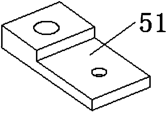
[0019] Specifically, if Figure 1 to Figure 3 As shown, it includes a base 1, a column 2, a sliding table 3, a cylinder placement platform 4, a pressing mechanism 5, a sliding seat 6, a servo motor 7, a three-phase asynchronous AC m...


PUM


Abstract

The invention discloses a laminate flooring edge groove forming device. The laminate flooring edge groove forming device comprises a base, vertical pillars, a sliding table, air cylinder holding platforms, compressing mechanisms, a sliding seat, a servo motor, a three-phase asynchronous alternate-current motor and a working platform. The lower ends of the vertical pillars are connected with the base, and the top ends of the vertical pillars are connected with the working platform. First connecting sleeves are arranged at the lower end of the sliding table and connected with the middles of thevertical pillars in a locking mode. A rack is arranged on the lateral surface of the sliding table. Second connecting sleeves are arranged at the lower ends of the air cylinder holding platforms. Thecompressing mechanisms are fixedly connected with the air cylinder holding platforms. Rolling wheels are arranged in the middle of the sliding seat, and the sliding seat is connected with the slidingtable through the rolling wheels. The servo motor is connected with the sliding seat. A gear is arranged on an output shaft of the servo motor and engaged with the rack. The three-phase asynchronous alternate-current motor is connected with the sliding seat, and a groove forming tool disc is arranged on an output shaft of the three-phase asynchronous alternate-current motor. Laminate flooring is fixed, a cutting tool moves and forms splicing edge grooves, and the straightness of the splicing edge grooves is guaranteed, so that the uniformity of splicing quality is guaranteed.

Description

technical field [0001] The invention belongs to the technical field of processing devices for building decoration boards, in particular, the invention relates to a device for opening and grooving reinforced floors. Background technique [0002] With the improvement of people's living standards, people's requirements for interior decoration are getting higher and higher. The current laminated flooring or wood-plastic panels are slotted on the splicing side, and the laminated floors or wood-plastic panels are transported on the transport rack. The fixed position is rotated so that the laminated floor or wood-plastic board walks over the cutting tool to complete the splicing side groove operation. The straightness of the spliced ​​side groove opened in this way is not high, so that the laminated floor or wood-plastic board is flat after assembly If the degree is not enough, it will affect the effect of construction and interior decoration. Contents of the invention [0003] ...

Claims


Application Information

Patent Timeline
IPC IPC(8): B27F5/02B27M3/04B26D3/06B26D5/08B26D7/02
Inventor 袁荣王涛吴倩倩
Owner 芜湖易迅生产力促进中心有限责任公司
Learn More