
Motor brake circuit and actuator

A circuit and steering gear technology, applied in the direction of AC motor deceleration device, electric motor/converter plug, stop device, etc., can solve the problem of large size, and achieve small size, adjustable braking resistance, and simple circuit structure Effect

Active Publication Date: 2018-01-16
UBTECH ROBOTICS CORP LTD
View PDF6 Cites 4 Cited by
  • Summary
  • Abstract
  • Description
  • Claims
  • Application Information

AI Technical Summary

Problems solved by technology

[0004] The purpose of the present invention is to provide a motor brake circuit and steering gear, aiming to solve the problem of excessive volume caused by the use of relays in the existing brake technology

Method used


Image

  • Motor brake circuit and actuator
  • Motor brake circuit and actuator

Examples


Embodiment Construction

[0016] In order to make the technical problems, technical solutions and beneficial effects to be solved by the present invention clearer, the present invention will be further described in detail below in conjunction with the accompanying drawings and embodiments. It should be understood that the specific embodiments described here are only used to explain the present invention, not to limit the present invention.

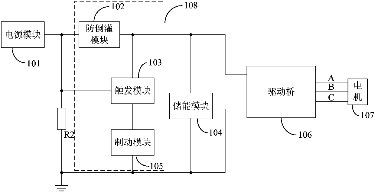
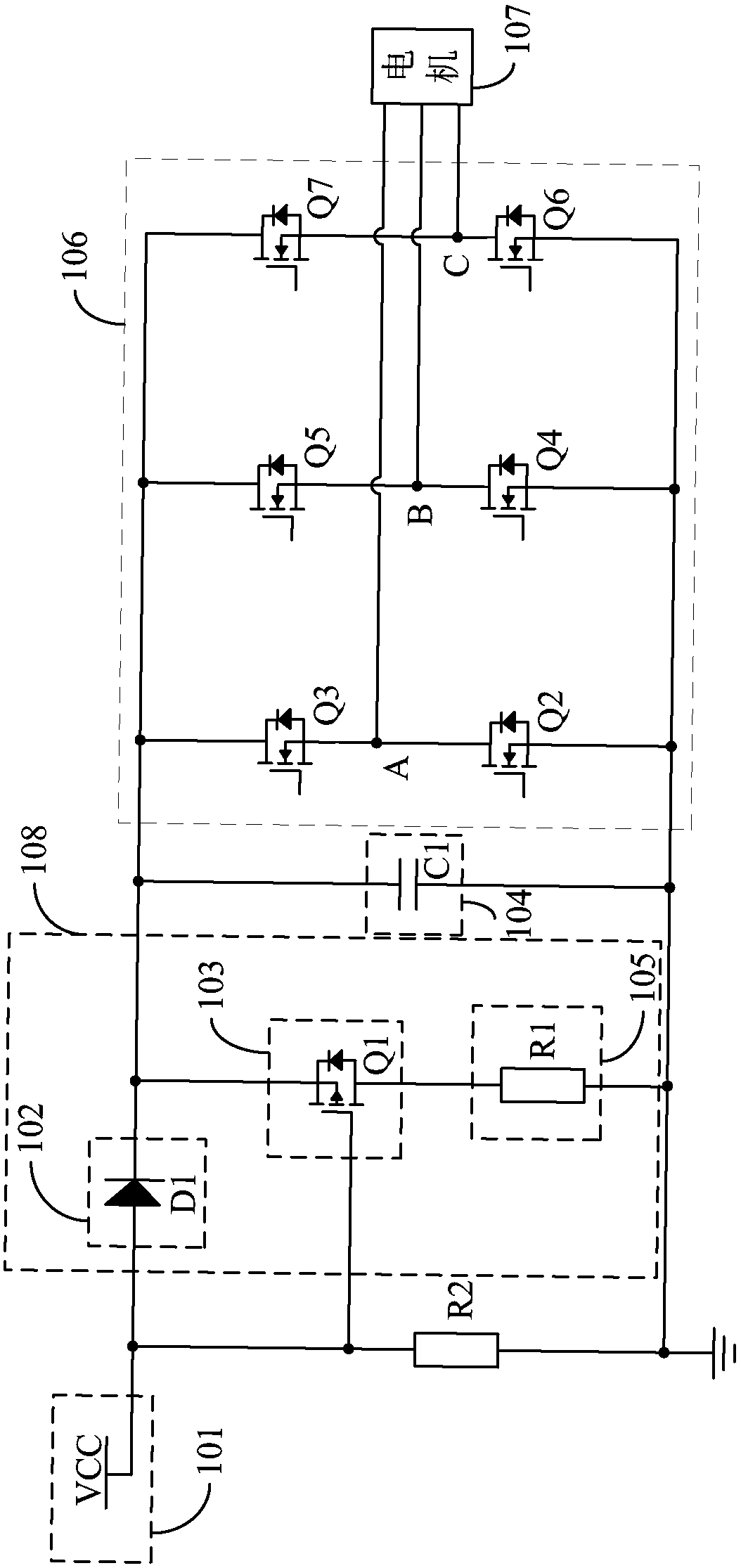
[0017] In the motor brake circuit and steering gear of the embodiment of the present invention, when the power supply module stops supplying power, the anti-backflow module can prevent the back electromotive force generated by the motor from being poured back into the power supply, and the voltage value of the back electromotive force generated by the motor reaches a preset threshold to turn on the system. The dynamic module consumes the counter electromotive force generated by the motor to brake the motor.

[0018] In order to illustrate the technical solutions of...


PUM


Abstract

The invention belongs to the technical field of electronic circuits and provides a motor brake circuit and an actuator. When a power supply module stops power supply, an anti-backflow module can prevent back electromotive force generated by a motor from flowing back to a power supply; and when a voltage value of the back electromotive force generated by the motor reaches a preset threshold, a brake module is connected to consume the back electromotive force generated by the motor to brake the motor, thereby achieving the effect of adjusting the brake resistance. Meanwhile, the circuit structure is simple, the volume is relatively small, and the effect of preventing the back electromotive force from being fed back to bus voltage can be achieved by adopting the anti-backflow module. In addition, the brake speed of the motor can be adjusted through adjusting a resistive parameter of the brake module, thereby solving the problem of over-large volume caused by the adoption of a relay in anexisting brake technology.

Description

technical field [0001] The invention belongs to the technical field of motor drive, and in particular relates to a motor braking circuit and a steering gear. Background technique [0002] The steering gear is the core component of the robot's movement. In the case of power failure, when the external drive rotates or the movement caused by its own gravity, the steering gear needs to have a certain braking ability, but the induced electromotive force generated by the external driving motor will affect other circuits. Part performance. Due to the small size of the steering gear, the area of ​​its circuit board is extremely tight. The traditional way is to use relays and other devices to short-circuit the bus voltage of the motor after the power is cut off, so that the back electromotive force generated by the motor will generate current in the coil to achieve the effect of braking. However, due to the use of relays, the volume is too large, so it is not suitable for applicatio...

Claims


Application Information

Patent Timeline
Patent Type & Authority Applications(China)
IPC IPC(8): H02P3/22H02P6/24
CPCY02T10/72
Inventor 熊友军赵计高范文华白熹
Owner UBTECH ROBOTICS CORP LTD
Learn More