
Method for measuring pitch deviation of cylindrical gear based on linear structured light

A linear structured light and deviation measurement technology, applied in measurement devices, optical devices, instruments, etc., can solve the problems of unreliable tooth profile data, inability to collect tooth profile data, and hindering the popularization and application of non-contact gear measurement.

Active Publication Date: 2018-01-16
BEIJING UNIV OF TECH
View PDF6 Cites 4 Cited by
  • Summary
  • Abstract
  • Description
  • Claims
  • Application Information

AI Technical Summary

Problems solved by technology

2. The data utilization rate of existing methods is low
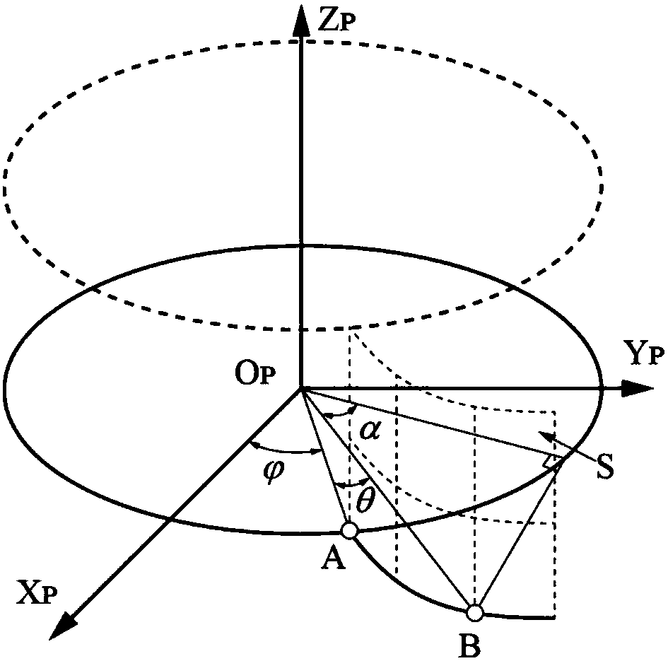
[0005] When measuring cylindrical gears with online structured light, there are three difficulties that hinder the popularization and application of non-contact gear measurement: First, the characteristics of structured light itself limit the measurement and cannot be directly measured in the radial direction.
Because the structured light is composed of a series of light spots with equal spacing, if the gear is directly projected radially to measure the gear, the measured tooth profile data will be unreliable
Second, due to the influence of the surface topography of each gear wheel, there will be shadow effects and tooth profile data cannot be collected
Third, the gear data measured by structured light is a parameter of a certain tooth profile relative to the spatial position of the probe, and this measurement parameter cannot be directly measured for the error term

Method used


Image

  • Method for measuring pitch deviation of cylindrical gear based on linear structured light
  • Method for measuring pitch deviation of cylindrical gear based on linear structured light
  • Method for measuring pitch deviation of cylindrical gear based on linear structured light

Examples


Embodiment Construction

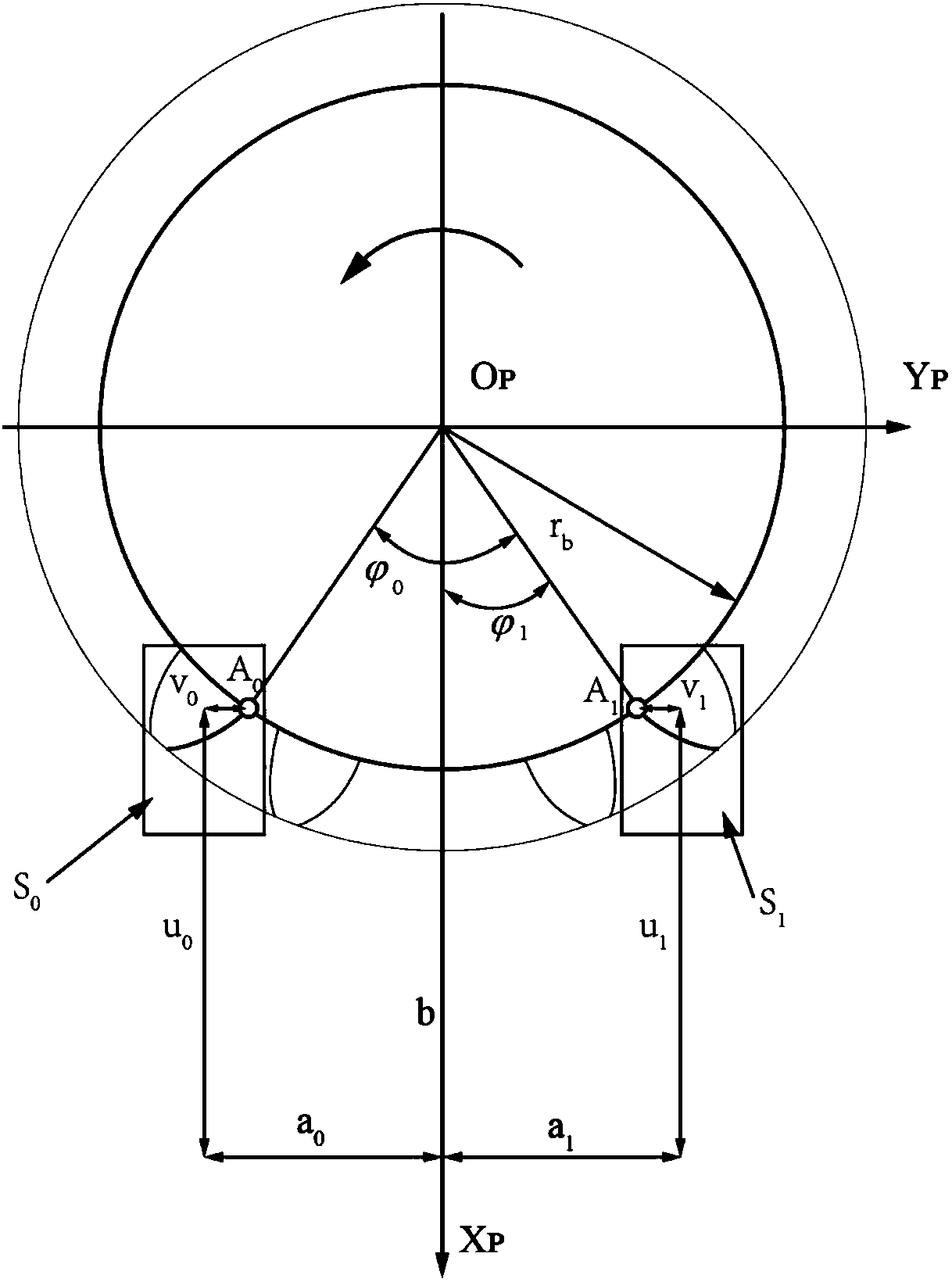
[0063] A method for measuring pitch deviation of cylindrical gears based on line structured light will be further described below in conjunction with the accompanying drawings.

[0064] like Figure 6.1-6.2 As shown, the method can be applied to both vertical measuring machines and horizontal measuring machines, and the horizontal measuring machine is taken as an example for illustration.

[0065] The horizontal measuring machine includes a spindle unit, a measuring unit and a machine bed, and the spindle unit and the measuring unit are installed on the bed. The main shaft unit includes a main shaft and a tailstock, the shaft circular grating is connected to the main shaft, and the Y-axis grating is installed on the Z-axis to measure the movement of the surveying and mapping unit along the Y direction; the surveying and mapping unit includes a Z-direction moving rod, an X-direction moving rod and a structured light probe. The Z-axis grating is installed on the Y-direction mov...


PUM


Abstract

The invention discloses a method for measuring the pitch deviation of a cylindrical gear based on linear structured light. The method comprises the steps of building a three-dimensional mathematical model of a tooth surface of a measured gear; and when the right surface of the gear is measured, adjusting an angle [phi]1 to enable the previous gear not to shield incident light shooting to the toothroot, thereby being capable of avoiding a shadow effect, and being credible in measurement data. The tooth profile of the gear is divided into a left tooth profile and a right tooth profile, two structured light measuring heads are adopted to measure the left tooth profile and the right tooth profile simultaneously, and the two measuring heads are installed according to a calculated offset parameter in order to improve the measurement efficiency. According to the invention, the gear pitch deviation mathematical model is built; and the built gear pitch deviation mathematical model is effectivefor evaluating the pitch deviation on both the left tooth profile and the right tooth profile. According to the method, pitch deviation measurement can be performed on all positions on the tooth profile, the data utilization rate is high, the initial position of the gear can be adapted through the angle [phi]1, and measurement can be performed immediately after the installation.

Description

technical field [0001] The invention discloses a method for measuring the tooth pitch deviation of a cylindrical gear based on line structured light, and belongs to the technical fields of precision testing technology, instrument and gear detection. Background technique [0002] One of the most important gear accuracy indicators for pitch deviation measurement, which reflects the indexing accuracy of the gear teeth and the unevenness of the distribution relative to the center of rotation. So far, the measurement method of the pitch deviation is not to determine the actual value of the pitch itself, but to reflect the pitch error by detecting the uniformity of the pitch. The main methods of measuring the pitch are divided into two categories: absolute measurement method and relative measurement method , there are actually three measurement methods: 1. Measuring the tooth pitch angle by means of circular grating or indexing disc; 2. The overall error measurement method, extrac...

Claims


Application Information

Patent Timeline
Patent Type & Authority Applications(China)
IPC IPC(8): G01B11/14
Inventor 石照耀王涛于渤
Owner BEIJING UNIV OF TECH
Learn More