
A corrugation measuring instrument for side-grinding rails on railway curves

A technology for measuring instruments and rails, applied in the engineering field, can solve the problems of accelerated development, defects, undetectable and elimination, etc., and achieve the effect of delaying the regeneration cycle and eliminating surface cracks

Active Publication Date: 2019-02-22
中铁物总运维科技有限公司
View PDF6 Cites 0 Cited by
  • Summary
  • Abstract
  • Description
  • Claims
  • Application Information

AI Technical Summary

Problems solved by technology

In recent years, with the application and popularization of rail grinding technology, it has gradually become one of the most important methods adopted by the public works department to solve rail defects by grinding rails with grinding cars, and most of the diseases can be better solved by grinding cars. However, rail corrugation often cannot be completely eliminated during grinding, which leads to very easy recurrence after grinding, and even accelerates development. The defects of existing detection methods are one of the main reasons for this problem
[0003] At present, there are a large number of rail corrugation detection methods and methods at home and abroad, but they are all aimed at the detection and analysis of the rail top. However, in engineering practice, the distribution range of corrugation is Usually it extends from the top of the rail to the inner side of the rail, that is, there are different degrees of corrugation on the entire wheel-rail contact surface
Therefore, it is often impossible to effectively detect and eliminate the rails on the inner side of the curve, resulting in wave grinding that cannot be completely eliminated after grinding

Method used


Image

  • A corrugation measuring instrument for side-grinding rails on railway curves
  • A corrugation measuring instrument for side-grinding rails on railway curves
  • A corrugation measuring instrument for side-grinding rails on railway curves

Examples


Embodiment Construction

[0024] The present invention will be described in further detail below in conjunction with the accompanying drawings.

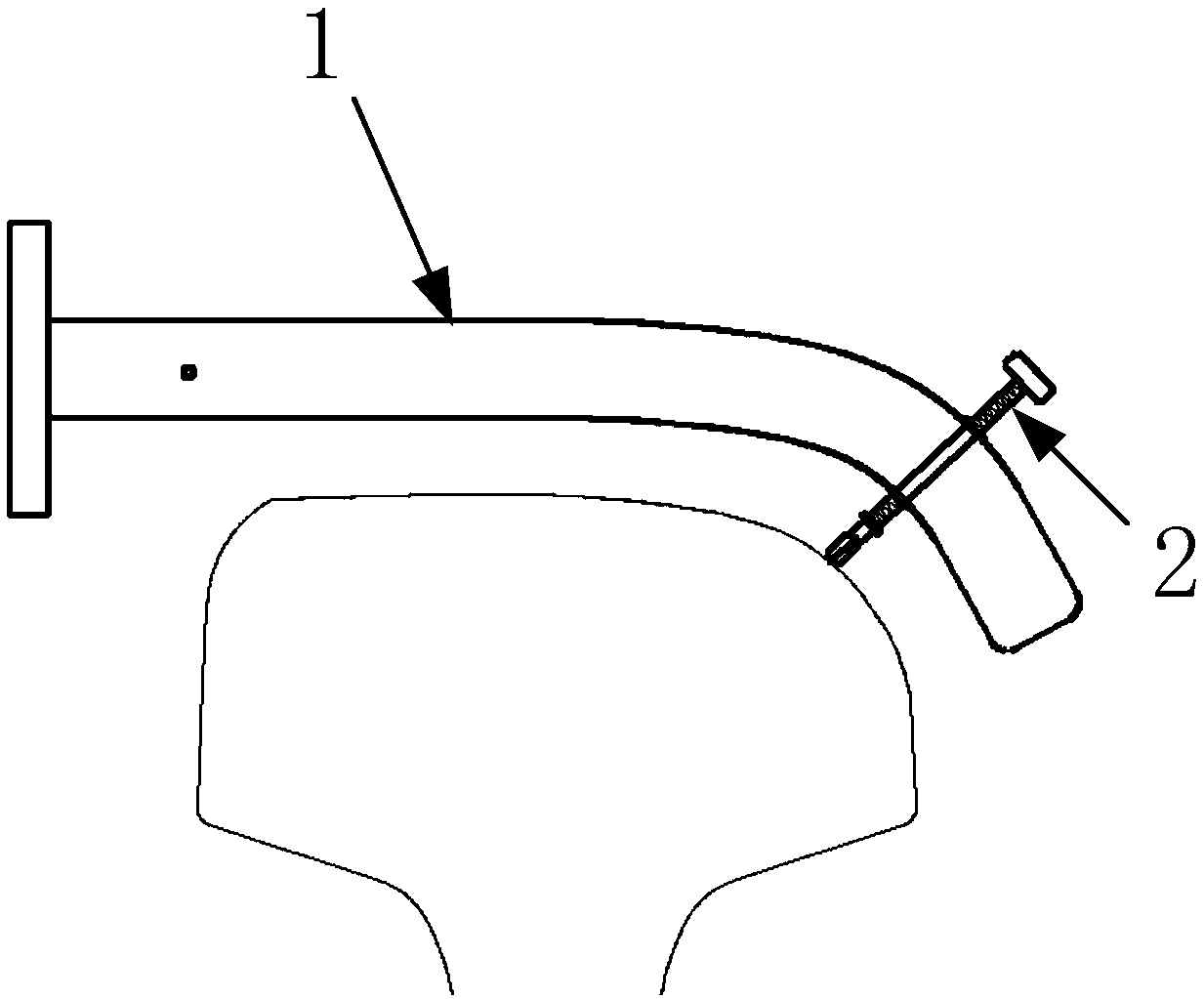
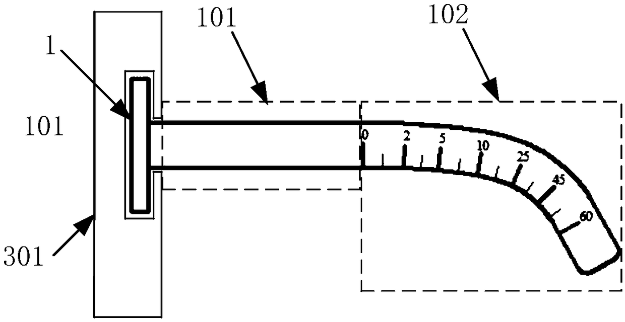
[0025] The rail corrugation measuring instrument of the present invention includes a measuring arm 1 and a displacement probe 2, such as figure 1 Shown; through the support frame 3 erected on the rail rail head.

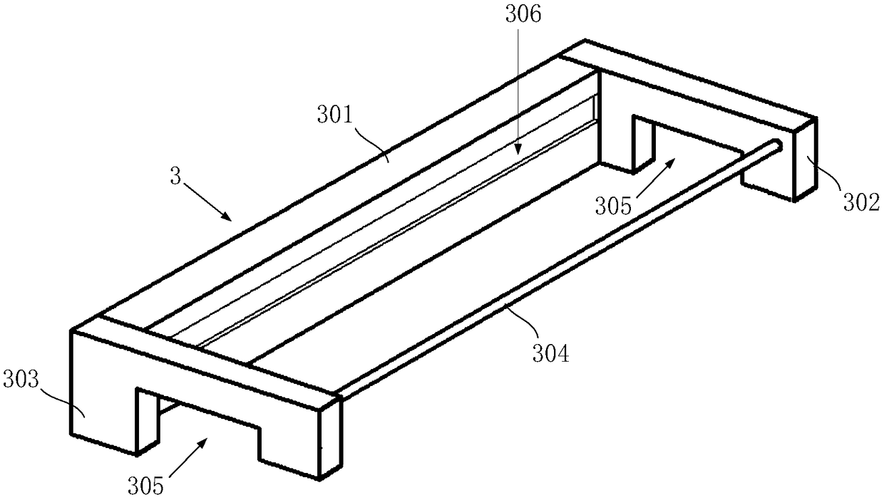
[0026] Described support frame 3 comprises side frame 301, front base 302, rear base 303 and connecting rod 304, as figure 2 shown. Wherein, the front base 302 and the rear base 303 are connected to each other through side frames 301 arranged along the direction of the rail; meanwhile, the front base 302 and the rear base 303 are connected to each other through a connecting rod 304 arranged along the direction of the rail. The connecting rod 304 stabilizes the structure of the supporting frame and facilitates the handling of the measuring instrument. The bottom of the front base 302 and the bottom of the rear base 303 are provided with a slot 30...


PUM


Abstract

The invention discloses a measuring apparatus for corrugation of a railway curve upper-part side grinding steel rail. A supporting frame with a measuring arm is erected on the steel rail; the measuring arm is mounted on the supporting frame in a sliding manner, and can longitudinally slide along the steel rail; a displacement probe is mounted on the measuring arm, and the angle of the displacementprobe on the surface of the steel rail can be adjusted; a measuring rolling wheel is mounted at the end part of the displacement probe, and is in contact with a rail head of the curve upper-part sidegrinding steel rail; the steel rail displacement probe moves along with the measuring arm in the direction of the steel rail, and the measuring rolling wheel rolls along the rail head of the curve upper-part side grinding steel rail; and in the moving process of the displacement probe, the movement capacity of the displacement probe is detected in a real-time manner by a displacement sensor mounted at the end part of the displacement probe, so that corrugation depth at a measured angle on the surface of the steel rail is obtained. Through the adoption of the measuring apparatus disclosed by the invention, the corrugation depth of the steel rail at different positions and angles, on the inner side of the curve side grinding steel rail can be detected, the curve steel rail grinding operation can be effectively guided, and thorough removing of the corrugation on the surface of the steel rail is facilitated.

Description

technical field [0001] The invention relates to the field of engineering technology, specifically, it is a method to detect the rail corrugation depth at different angles of the rail surface by optimizing the structure of the measuring arm, especially the rail corrugation depth at different angles of the strand side grinding rail surface on the curve, to form rail corrugation. Grinding waveform diagram, so as to effectively guide the rail wave grinding operation. Background technique [0002] The railway is the main artery of transportation, which plays a very important role in the development of the national economy. With the increase of the speed of the railway, the increase of the transport volume, and the diversification of the operating models, the loads on the rails are becoming more and more complex, resulting in wave wear on the rails, rail Surface scratches, rail surface peeling, rail side wear, cracks and rail head crushing and other diseases have a serious impact ...

Claims


Application Information

Patent Timeline
Patent Type & Authority Patents(China)
IPC IPC(8): B61K9/08G01B21/18
Inventor 王军平
Owner 中铁物总运维科技有限公司
Learn More