Collimator, imaging equipment, focal position tracing method and correcting method

A focal position and imaging equipment technology, which is applied in the directions of instruments and applications for radiological diagnosis, diaphragms for radiological diagnosis, etc., can solve the problems of artifacts such as reconstructed images, and achieve the purpose of reducing artifacts, improving utilization, and improving signal-to-noise. the effect of

Active Publication Date: 2018-01-16
SHANGHAI UNITED IMAGING HEALTHCARE
View PDF9 Cites 8 Cited by
  • Summary
  • Abstract
  • Description
  • Claims
  • Application Information

AI Technical Summary

Problems solved by technology

Artifacts in the reconstructed image due to air correction and patient scan may not be in the same focal position

Method used


Image

  • Collimator, imaging equipment, focal position tracing method and correcting method
  • Collimator, imaging equipment, focal position tracing method and correcting method
  • Collimator, imaging equipment, focal position tracing method and correcting method

Examples


Embodiment Construction

[0045] In order to make the above objectives, features and advantages of the present invention more obvious and understandable, the specific implementation of the present invention will be described in detail below with reference to the accompanying drawings and embodiments.

[0046] The imaging system involved in the present invention can be used not only for medical imaging, such as disease diagnosis and research, but also for industrial fields. The imaging system may be a single-modal system or a multi-modal system, including but not limited to, a computed tomography (CT) system, a positron emission tomography (PET) system, and a magnetic resonance imaging (magnetic resonance imaging, MRI) system, ultrasound scan (ultrasound, US) system, single-photon emission computed tomography (SPECT) system, PET-CT, US-CT, PET-MRI, etc. or Multiple combinations.

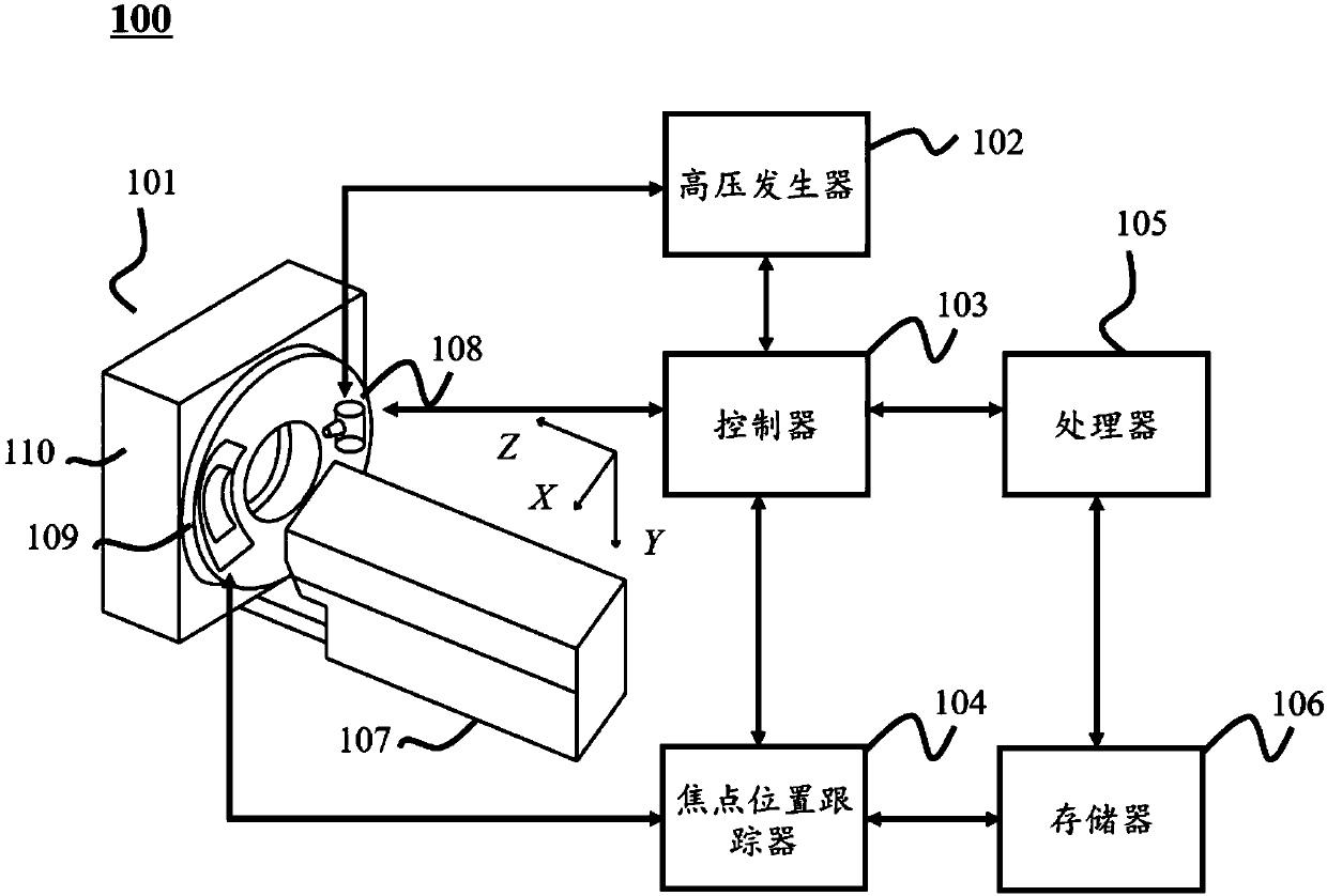
[0047] figure 1 It is a schematic diagram of the imaging system of the present invention. The imaging system 100 can scan a tar...


PUM


Abstract

The invention discloses a computed tomography data correcting method. The method includes the steps that a reference object is scanned, and first detector response corresponding to the first focal position is obtained; the target object is scanned, and second detector response corresponding to the second focal position is obtained; a correction table is inquired, third detector response corresponding to the first focal position and fourth detector response corresponding to the second focal position are determined, and the correction table comprises the corresponding relation between differentfocal positions and detection response; based on the third detector response and the fourth detector response, the first detector response is corrected; imaging data corresponding to the target objectis obtained based on the first detector response and the second detector response obtained after correction. By correcting computed tomography data, image artifacts caused by focal position offset are reduced or eliminated, and imaging quality is improved.

Description

【Technical Field】 [0001] The present application relates to the field of imaging, and in particular to a method for tracking the focus position in a computed tomography (CT) equipment and a method for correcting the deviation of the focus position. 【Background technique】 [0002] In the process of computed tomography (CT), the X-ray tube is affected by the surrounding environment and other factors, which will cause the focus position of the X-ray beam to change. For example, due to the accumulation of heat, the X-ray tube rotation axis thermally expands, resulting in the focus position Offset affects imaging. Moreover, due to environmental changes, air correction is required during CT imaging. The focus position of the air correction and the patient scan may not be the same position, resulting in artifacts in the reconstructed image. Therefore, there is a need for a method of tracking the X-ray focus position to reduce or eliminate the impact on imaging. [Content of the invent...

Claims


Application Information

Patent Timeline
Patent Type & Authority Applications(China)
IPC IPC(8): A61B6/03A61B6/06G01N23/04
CPCA61B6/4021A61B6/405A61B6/4291A61B6/542A61B6/547A61B6/582A61B6/586A61B6/06A61B6/032G21K1/025A61B6/585
Inventor 李兵
Owner SHANGHAI UNITED IMAGING HEALTHCARE
Why Eureka
Try Eureka