Moisture-proof magnetic isolating device for transformer
A transformer and magnetic isolation technology, applied in transformer/inductor cooling, transformer/inductor parts, transportation and packaging, etc., can solve the problems of magnetic flux leakage, electromagnetic pollution, electromagnetic pollution of the surrounding environment, etc., to ensure stability , the effect of good storage
- Summary
- Abstract
- Description
- Claims
- Application Information
AI Technical Summary
Problems solved by technology
Method used
Image
Examples
Embodiment 1
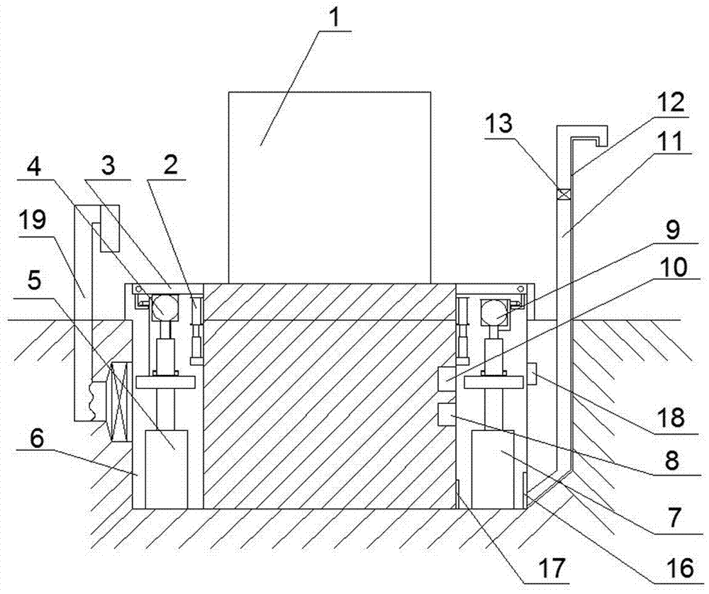
[0053] A transformer moisture-proof and magnetic isolation device, including a safety slot 6 arranged on the peripheral side of the transformer body 1, a protection mechanism arranged in the safety slot 6, a guard plate mechanism arranged on the safety slot 6, and a protection mechanism arranged on the safety slot 6. The safety mechanism in the safety groove 6, the drying mechanism 19 that is arranged in the described safety groove and cooperates with the described safety mechanism, and is arranged in the described safety groove and is used to cooperate with the described protection mechanism, guard plate mechanism, safety mechanism A control mechanism connected to the drying mechanism;
[0054] The safety groove 6 is a plurality of rectangular grooves arranged on the side of the transformer body 1 and connected end to end;
[0055] The drying mechanism includes a drying fan 194 arranged on the inner wall of the rectangular groove, a drying pipe 193 arranged at the rear of the...
Embodiment 2
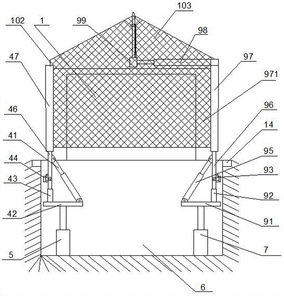
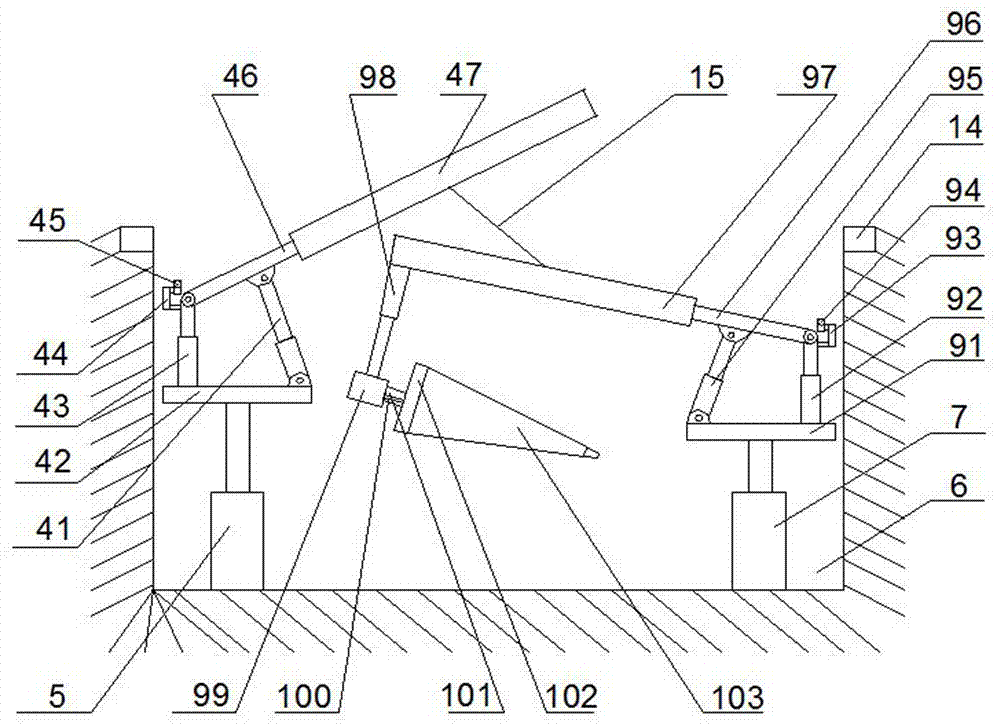
[0070] It differs from Embodiment 1 in that: a top protection module is provided at the top of the winding bin 97, and the top protection module includes a first top telescopic rod 98 arranged on the winding bin 97, which is arranged on the first The top rotary platform 94 on the top telescopic link 98, the second top telescopic link 101 that is arranged on the top rotary platform 94, the shielding umbrella 103 that is arranged on the second top telescopic link 101, is arranged on the top rotary The third top telescopic pole 100 adjacent to the second top telescopic pole 101 on the platform 94 is used to control the opening and closing of the shielding umbrella 103 .
[0071] The first top telescopic rod 98 is arranged on the upper end of the winding bin 97 through an angle adjustment motor arranged on the upper end of the winding bin 97 .
[0072] The umbrella surface of the shielding umbrella 103 is a metal mesh surface, and a bridging mesh surface 102 is provided on the low...
Embodiment 3
[0075] Such as image 3 and 14 As shown: the difference between it and the second embodiment is that the guard plate body 3 used is composed of two long plates 33 and two short plates 34. This design method can reduce the complexity of the mechanism. A pressure plate structure is provided at the junction to ensure that the short boards can also be locked when the long boards are stored and combined.
PUM
 Abstract
Description
Claims
Application Information
 - Generate Ideas
- Intellectual Property
- Life Sciences
- Materials
- Tech Scout
- Unparalleled Data Quality
- Higher Quality Content
- 60% Fewer Hallucinations
Browse by: Latest US Patents, China's latest patents, Technical Efficacy Thesaurus, Application Domain, Technology Topic, Popular Technical Reports.
© 2025 PatSnap. All rights reserved.Legal|Privacy policy|Modern Slavery Act Transparency Statement|Sitemap|About US| Contact US: help@patsnap.com


