
Lamp

A technology for lamps and lamp tubes, which is applied in the direction of lampshades, lighting devices, cooling/heating devices of lighting devices, etc., can solve the problems of poor heat dissipation, poor heat dissipation performance, and limited heat dissipation effect, and achieve the goal of improving heat dissipation efficiency and efficiency Effect

Inactive Publication Date: 2018-01-12
李玲玲
View PDF6 Cites 0 Cited by
  • Summary
  • Abstract
  • Description
  • Claims
  • Application Information

AI Technical Summary

Problems solved by technology

[0004] However, limited by the structure of the aluminum substrate, its heat dissipation effect is limited, and it is difficult to meet the requirements of high-power, high-brightness and high-heating lamps. Furthermore, the shell of the lamp is usually made of plastic, and its heat dissipation performance is poor. More The ground plays the role of protection and decoration, but it will affect the heat dissipation path between the aluminum substrate and the outside air, and the heat dissipation effect is poor, especially difficult for high-power, high-brightness and high-calorie lamps.

Method used


Image

  • Lamp
  • Lamp

Examples


Embodiment Construction

[0017] The present invention will be further described in detail below in conjunction with the accompanying drawings and specific embodiments.

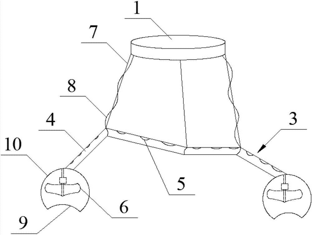
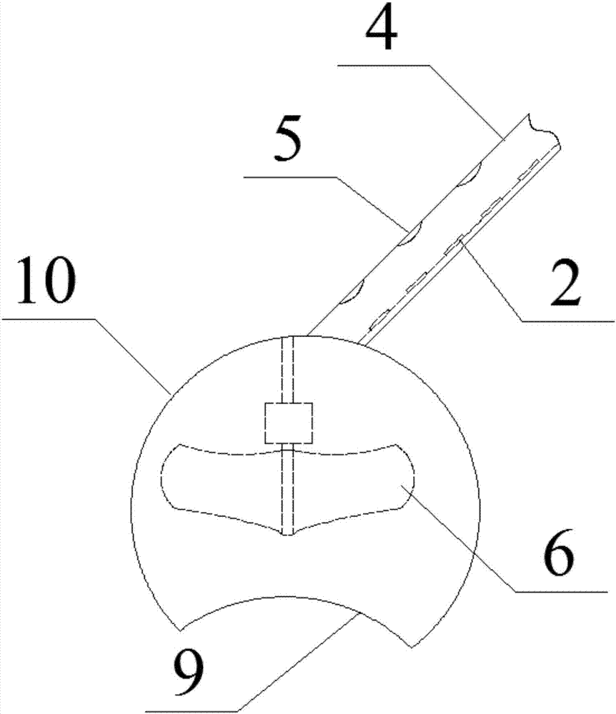
[0018] Such as figure 1 , figure 2 The lamp shown includes a chassis and LED components, and also includes a special-shaped transparent lamp tube; the lamp tube is divided into multiple sub-tubes, each sub-tube is connected internally, and the adjacent sub-tubes are set in different directions; the upper end of the tube A plurality of heat dissipation holes are provided, and the LED components are arranged inside the lamp tube along the central axis of the lamp tube; the end of the lamp tube communicates with the outside and is equipped with a cooling fan; the upper end of the lamp tube is connected to the chassis through connecting wires and wires. Preferably, the wires are wound on the connecting wires, and the chassis is fixed on the ceiling.

[0019] The outer cover of the cooling fan is provided with a cover body; the inside o...


PUM


Abstract

The invention discloses a lamp. The lamp comprises a base plate and an LED component, and further comprises a special-shaped transparent lamp tube, wherein the lamp tube is divided into a plurality ofsections of lamp sub-tubes; the lamp sub-tubes communicate with each other at the inner parts; every two adjacent lamp sub-tubes are arranged in different directions; a plurality of heat dissipationholes are formed in the upper end of the lamp tube; the LED component is arranged in the lamp tube in the middle axis direction of the lamp tube; the tail ends of the lamp tube communicate with the outside, and a cooling fan is arranged at each of the tail ends; and the upper end of the lamp tube is connected with the base plate through connecting wires and guide wires. The lamp has the benefits as follows: the plurality of heat dissipation holes are formed in the upper end of the lamp tube, the cooling fans are arranged at the two ends of the lamp tube separately, the heat in the lamp tube isquickly discharged to the outside, and the heat dissipation efficiency of the lamp tube is improved; and besides, the lamp tube is divided into the plurality of sections of lamp sub-tubes with different extending directions, so that the outside cold air flow and the hot air flow in the lamp tube can cause more collisions in the lamp tube, and the efficiency of the hot air flow being discharged from the upper end of the lamp tube is increased.

Description

technical field [0001] The invention relates to the field of heat dissipation of lamps, in particular to a lamp. Background technique [0002] At present, LEDs, or light-emitting diodes, can directly and efficiently convert electrical energy into visible light, and have a service life of tens of thousands to hundreds of thousands of hours. Lamps that use LEDs as light sources are called LED lamps, which are known as the most commonly used daily lamps for their high quality, durability, and energy-saving advantages. [0003] Usually, the light-emitting components need to be installed on the aluminum substrate, and then the aluminum substrate is installed on the shell of the lamp. The heat generated by the light-emitting component needs to be transferred to the aluminum substrate when it is normally illuminated, and then transferred to the outside air through the casing. In order to achieve the cooling effect. [0004] However, limited by the structure of the aluminum substr...

Claims


Application Information

Patent Timeline
Patent Type & Authority Applications(China)
IPC IPC(8): F21K9/20F21V29/83F21V29/67F21V3/04F21V31/00F21Y115/10
Inventor 李玲玲
Owner 李玲玲
Learn More