
A sealing gas nozzle and an air bag using the gas nozzle

A technology of air nozzles and airbags, which is applied to valves, valve devices, and control valves used for inflation. It can solve problems such as shaking, damage, and restricting the development of offshore operations, so as to reduce processing costs, improve service life, and ensure sealing effects. Effect

Active Publication Date: 2019-11-08
QINGDAO DUQIU NEW ENERGY TECH CO LTD
View PDF8 Cites 2 Cited by
  • Summary
  • Abstract
  • Description
  • Claims
  • Application Information

AI Technical Summary

Problems solved by technology

Most of the existing buoyancy devices use buoyancy balls. The outside of the buoyancy ball structure is generally made of hard plastic, and the inside is filled with foam plastic. The buoyancy ball made of this structure will bear all the pressure during its use. It is easily damaged by sea waves and sea winds, etc., resulting in the failure of many offshore operations, which seriously limits the development of offshore operations
[0003] There is also a kind of buoyancy device, which uses inflatable buoyancy balls to provide certain buoyancy to the work platform, which has the advantages of light weight and high buoyancy. However, this buoyancy device has the following problems: after the inner tank in the shell is inflated, the During the process, due to the influence of waves and sea wind, shaking occurs, and the shell is easily torn where the inflatable nozzle passes through; the connection between the inner tank and the inflatable nozzle is prone to air leakage, which makes the buoyancy device unable to meet the floating requirements of the work platform , affecting the continuation of offshore operations

Method used


Image

  • A sealing gas nozzle and an air bag using the gas nozzle
  • A sealing gas nozzle and an air bag using the gas nozzle
  • A sealing gas nozzle and an air bag using the gas nozzle

Examples


Embodiment Construction

[0030] In order to make the objectives, technical solutions, and advantages of the present invention clearer, the following further describes the present invention in detail with reference to the accompanying drawings and embodiments. It should be understood that the specific embodiments described herein are only used to explain the present invention, but not to limit the present invention.

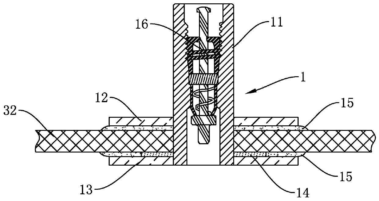
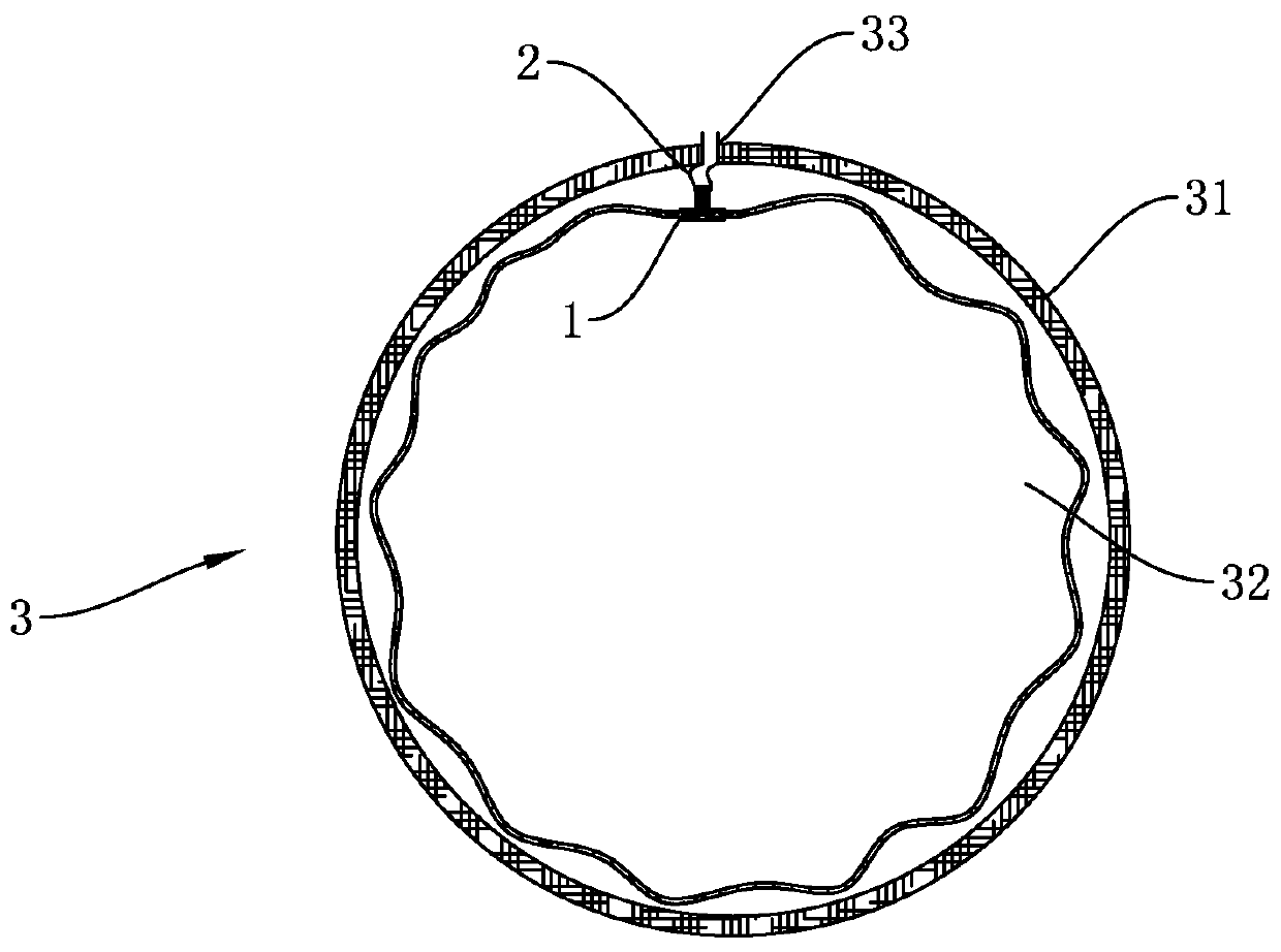
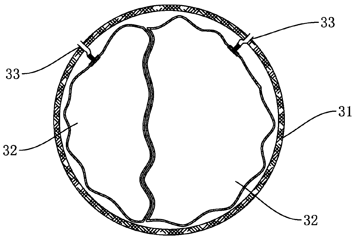
[0031] Such as figure 1 As shown, a sealed gas nozzle in the present invention is arranged on the inner liner 32. The sealed gas nozzle includes a trachea 11 and an annular fixing piece; the fixing piece includes an outer fixing piece 12 and an inner fixing piece 13, and the outer fixing piece 12 and The outer surface of the inner liner 32 is adhesively connected, and the inner fixing sheet 13 is adhesively connected to the inner wall surface of the inner liner 32; the trachea 11 is a rigid tube, and the inner end of the trachea 11 is fixedly connected to the through hole of the inner fixing ...


PUM


Abstract

The invention discloses a sealing air nozzle arranged on an inner container. The sealing air nozzle comprises an air pipe and annular fixing pieces. The fixing pieces comprise the fixing piece on theouter side and the fixing piece on the inner side. The fixing piece on the outer side is in adhesive connection with the outer surface of the inner container, and the fixing piece on the inner side isin adhesive connection with the inner wall face of the inner container. The air pipe is a rigid pipe. The inner side end of the air pipe penetrates through a through hole in the fixing piece on the outer side and a through hole in the inner container, and is fixedly connected with a through hole in the fixing piece on the inner side. The outer side end of the air pipe is located on the outer sideof the fixing piece on the outer side. The invention further discloses an air bag adopting the sealing air nozzle. In the using process of the sealing air nozzle, a reliable buoyancy guarantee can beprovided for operation at sea, meanwhile, the service life of the sealing air nozzle is prolonged, and the sealing air nozzle has the advantages of being simple in structure, convenient to manufacture and low in cost.

Description

Technical field [0001] The invention relates to the technical field of inflatable sealing devices, in particular to design a sealed gas nozzle and an airbag using the gas nozzle. Background technique [0002] When conducting marine aquaculture operations, the buoyancy device is a must-equipped tool, because the buoyancy device can provide a certain buoyancy for the offshore operation platform, so that the operation platform can float on the sea. Existing buoyancy devices mostly use buoyancy balls. The outer structure of the buoyancy ball is generally made of hard plastic, and the inside is filled with foamed plastic. The buoyancy ball composed of this structure is used by the external hard plastic to withstand all the pressure. It is easily damaged by sea waves and sea breeze, resulting in many offshore operations that cannot be implemented well and severely restricting the development of offshore operations. [0003] There is also a buoyancy device that uses an inflatable buoyanc...

Claims


Application Information

Patent Timeline
Patent Type & Authority Patents(China)
IPC IPC(8): F16K24/06F16K15/20B63B35/44
Inventor 成立
Owner QINGDAO DUQIU NEW ENERGY TECH CO LTD
Learn More