
Pressure determination in a fuel injection valve

A pressure and fuel technology, applied in the direction of fuel injection control, electrical control, machine/engine, etc., can solve the problem of insufficient accuracy of pressure measurement, and achieve the effect of improving injection accuracy, avoiding emissions, and accurate pressure determination

Active Publication Date: 2018-01-09
VTESCO TECH GMBH
View PDF6 Cites 1 Cited by
  • Summary
  • Abstract
  • Description
  • Claims
  • Application Information

AI Technical Summary

Problems solved by technology

Furthermore, in some cases pressure measurements by means of pressure sensors may not have sufficient accuracy

Method used


Image

  • Pressure determination in a fuel injection valve
  • Pressure determination in a fuel injection valve
  • Pressure determination in a fuel injection valve

Examples


Embodiment Construction

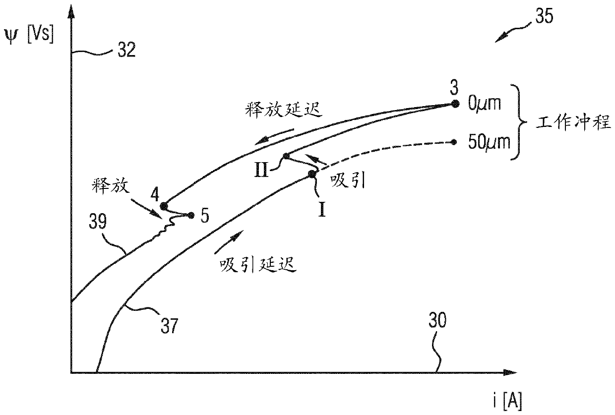
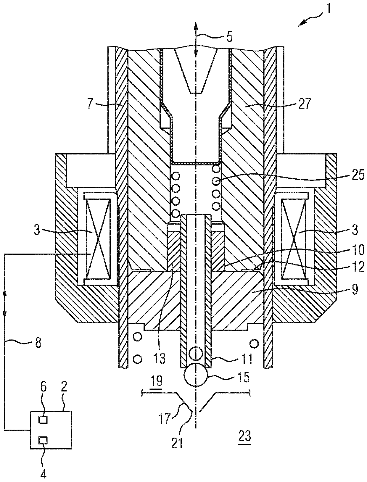
[0045] figure 1 The solenoid valve 1 shown in schematic cross-sectional view in , has a coil 3 to which a voltage can be applied, so that current flows through the coil 3 in order to build up a magnetic field. In this context, the magnetic field extends substantially in the longitudinal direction 5 of the guide cylinder 7 . The magnetic field acts on the ferromagnetic armature 9 which can move within the guide cylinder 7 . By moving the armature 9 it is possible to move the closing element or the nozzle needle 11 of the solenoid valve 1 in the longitudinal direction 5 , in particular by making contact between the armature 9 and the annular drive element 13 which is fixedly connected to the closing element 11 .

[0046] exist figure 1 In the open state shown in , the closing ball 15 constituted by a conical seat 17 is drawn back so that fuel 19 can pass through the opening 21 in the seat into the combustion chamber 23 for combustion. In the fully open state, the armature 9 ...


PUM


Abstract

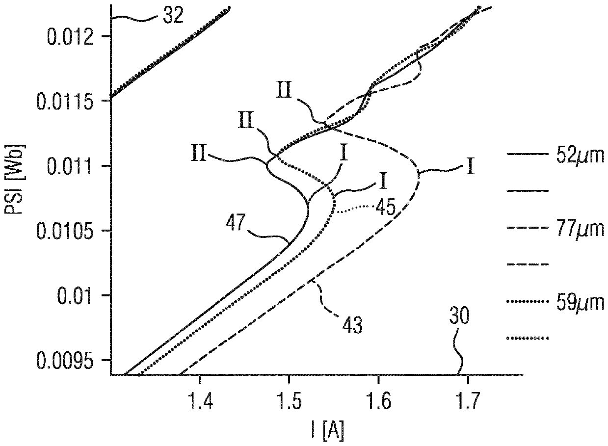
The invention provides a device and a method for determining a pressure of a fuel (19) which is provided for being injected by way of a controllable closure element (11) of a solenoid valve (1) into acombustion chamber (23), wherein the method has: generating an electrical current flow (i) through a coil (3) of the solenoid valve (1) in order to generate a magnetic field in order to generate a magnetic force on an armature (9), which magnetic force displaces the armature (9) in a direction for opening the closure element (11); determining a magnitude of a magnetic flux ([psi]) of the magneticfield before or when a first state (I) is attained in which the armature begins to displace the closure element; and determining the magnitude of the pressure on the basis of the determined magnitudeof the magnetic flux.

Description

technical field [0001] The invention relates to a method and a device for determining the pressure of a fuel, wherein the magnetic flux within a solenoid valve is used for this purpose. Furthermore, the invention relates to a pressure measuring system with a solenoid valve and a device for determining the pressure of the fuel. Background technique [0002] A fuel injection system usually consists of an electronic part and a hydraulic part. In the hydraulic part the fuel is compressed to a predetermined pressure so that during injection into a combustion chamber such as eg a cylinder an optimal atomization can be employed to introduce the required or desired fuel quantity. In order to carry out this method correctly, the fuel pressure, usually measured by means of a pressure sensor, must be known. Errors or deviations of the measured fuel pressure from the actual fuel pressure can lead to deviated injection quantities, to non-optimal atomization of the fuel, and thus to wor...

Claims


Application Information

Patent Timeline
Patent Type & Authority Applications(China)
IPC IPC(8): F02D41/20
CPCF02D41/20F02D2041/2055F02D2041/2058F02D2200/0604F02D2041/2003
Inventor C.豪泽G.勒泽尔M.斯图蒂卡
Owner VTESCO TECH GMBH
Learn More