[0010]Therefore, it is desirable to make it possible to easily stabilize the height of a liquid surface in a subtank (auxiliary tank) that temporarily stores ink (liquid) prior to supplying the ink to a liquid discharging head (consumption object that consumes the liquid), and to make it possible to achieve a small, low-cost device.
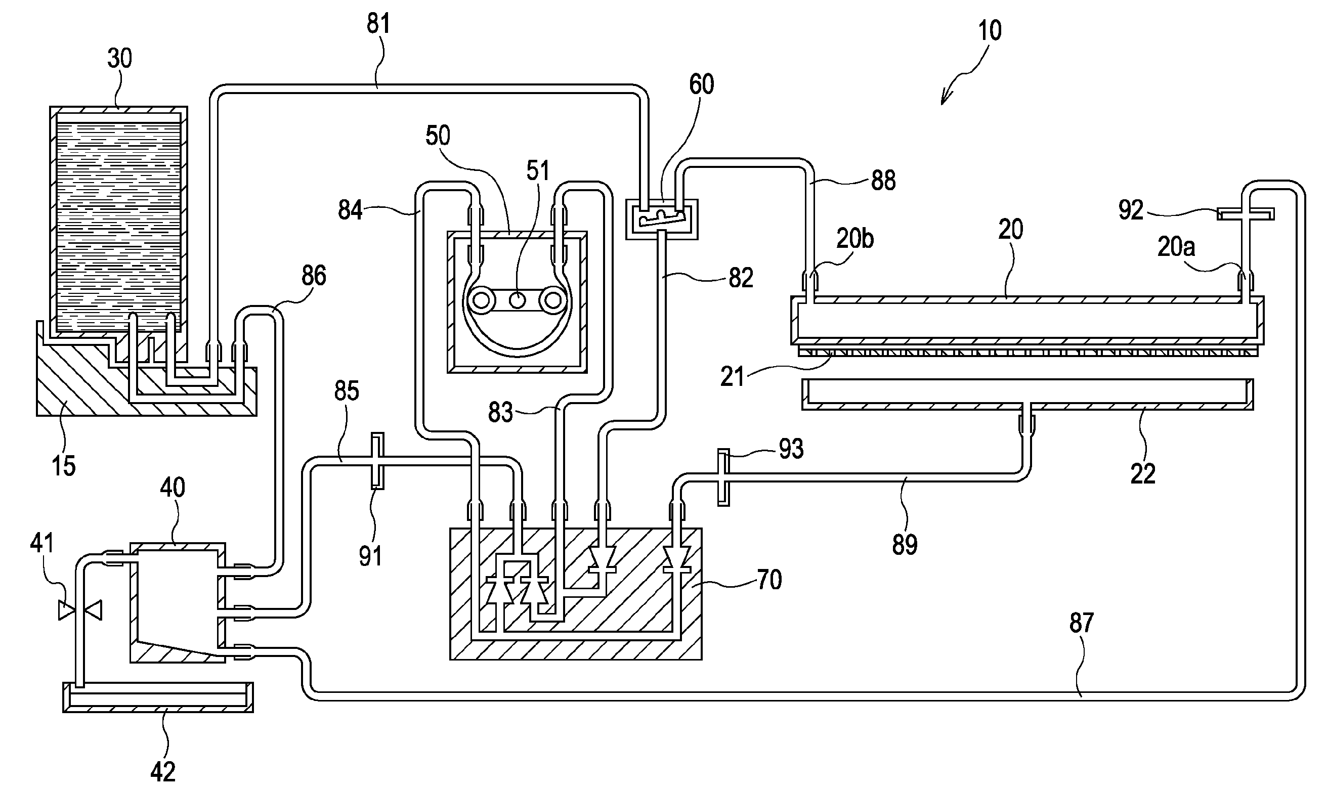
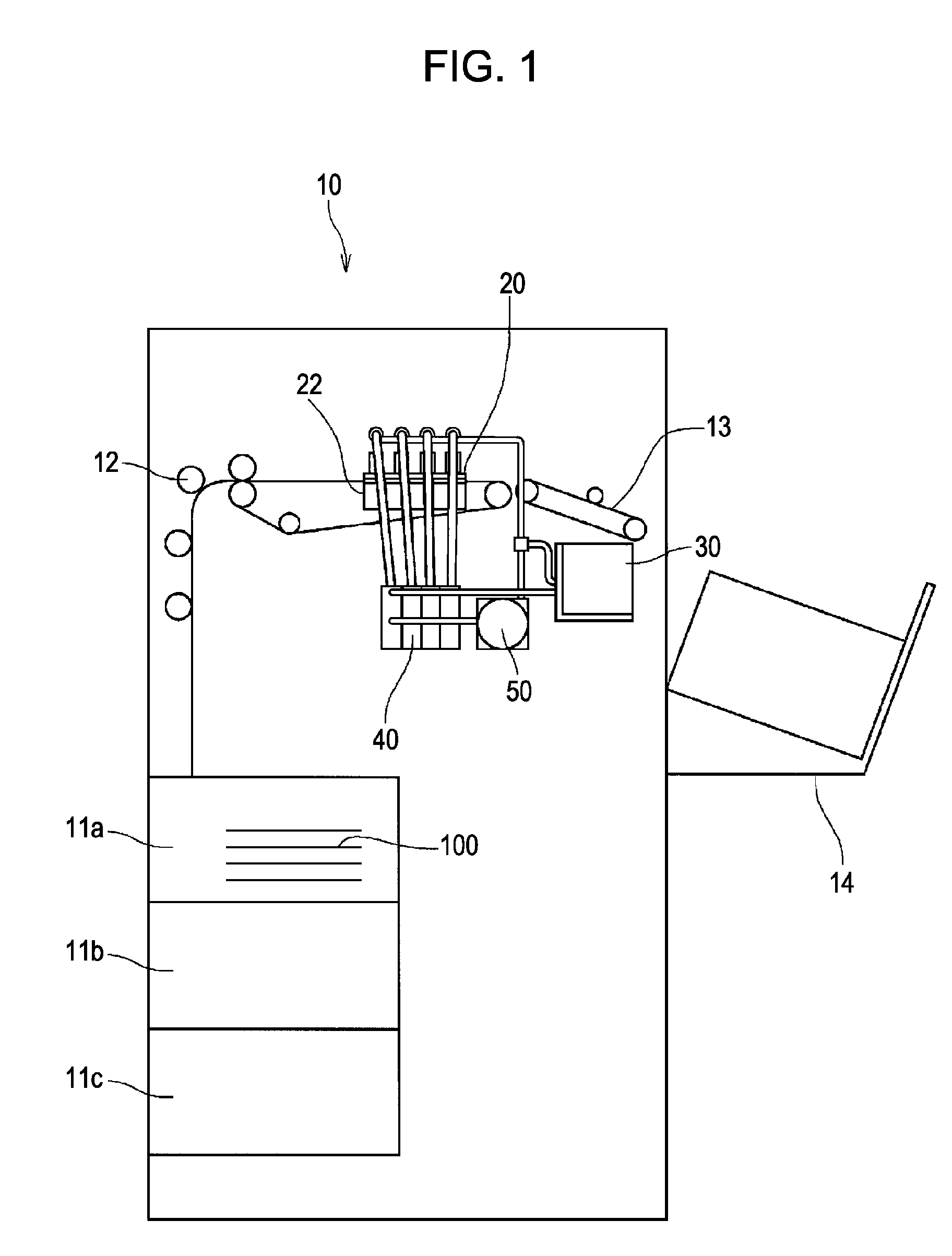
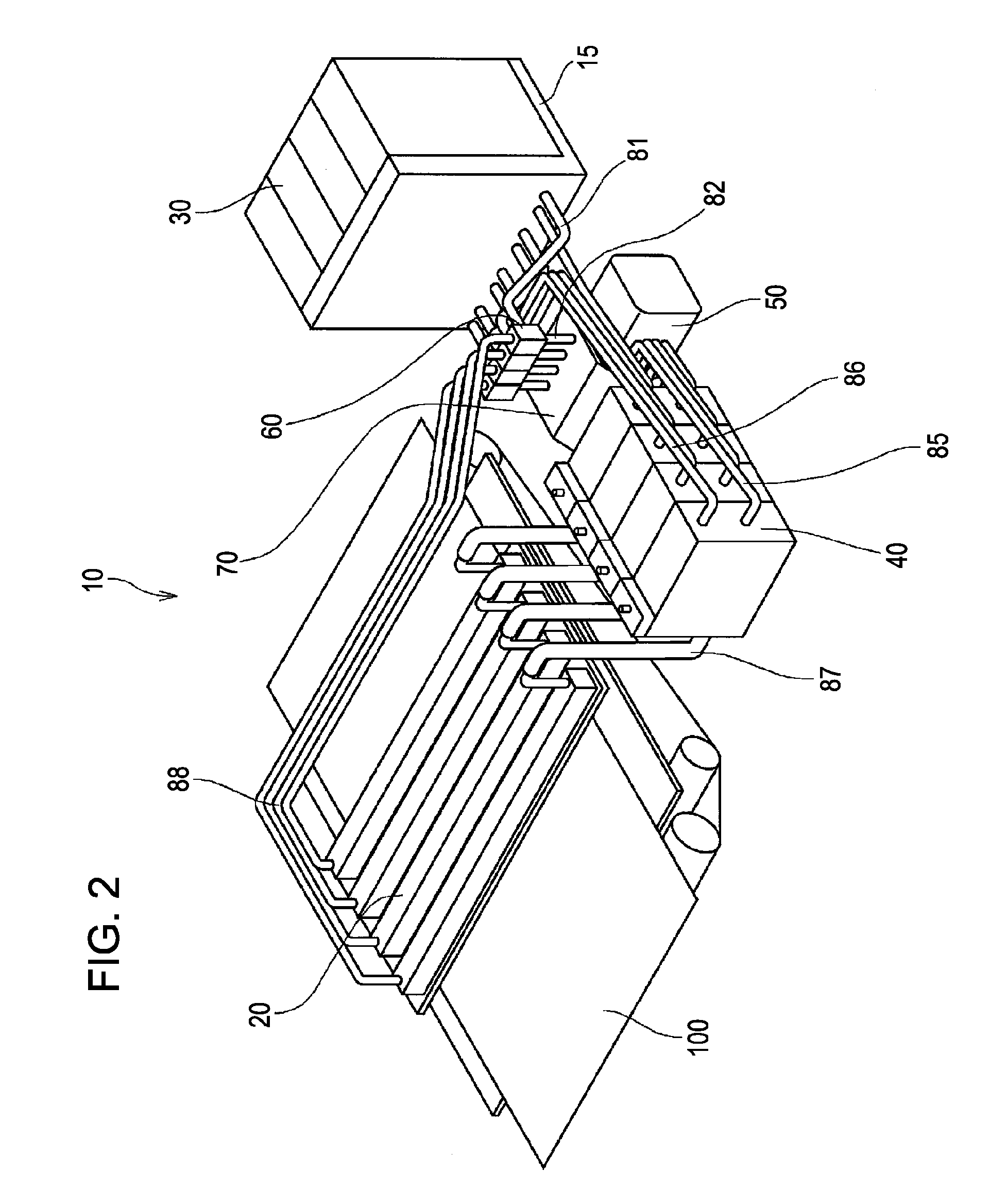
[0015]According to the another embodiment of the present invention, the liquid stored in the liquid tank is transferred by the transfer pump, and is temporarily stored in the auxiliary tank prior to supplying the liquid to the liquid discharging head. Then, when the liquid stored in the auxiliary tank becomes greater than or equal to the certain amount, the liquid is returned to the liquid tank from the auxiliary tank by the return
pipe. Therefore, in the liquid discharging device that discharges the liquid from a
nozzle of the liquid discharging head, the liquid in the auxiliary tank, provided in a transfer path for transferring the liquid to the liquid discharging head, does not become greater than or equal to the certain amount. As a result, the pressure of the liquid in the liquid discharging head is maintained in a proper range that is in accordance with the height of a liquid surface in the auxiliary tank.
[0016]According to still another embodiment of the present invention, there is provided a method of controlling a liquid discharging device. The liquid discharging device includes a liquid discharging head capable of discharging supplied liquid from a
nozzle, a liquid tank storing the liquid that is discharged by the liquid discharging head, a transfer pump for transferring the liquid stored in the liquid tank, a controlling device for controlling driving of the transfer pump, an auxiliary tank temporarily storing the liquid transferred by the transfer pump before supplying the liquid to the liquid discharging head, the auxiliary tank being disposed below the nozzle so that pressure of the liquid in the liquid discharging head is a negative pressure, and a return
pipe disposed so as to return the liquid to the liquid tank from the auxiliary tank when an amount of the liquid stored in the auxiliary tank becomes greater than or equal to a certain amount. The method includes the step of driving the transfer pump so that t≧(Q / V) by the controlling device, where a driving time for driving the transfer pump is t, an amount of the transfer of the liquid per unit time by the transfer pump is V, and an amount of change of the liquid in the auxiliary tank is Q, the amount of change of the liquid in the auxiliary tank allowing, with respect to
atmospheric pressure, the pressure of the liquid in the liquid discharging head to be maintained at the negative pressure in a range allowing the liquid to be stably discharged while preventing leakage of the liquid from the nozzle.
[0018]According to the liquid supplying device of the embodiment of the present invention, when the liquid stored in the auxiliary tank becomes greater than or equal to the certain amount, the liquid is returned to the liquid tank from the auxiliary tank by the return pipe. Therefore, in the liquid supplying device that supplies the liquid to the consumption object, the liquid in the auxiliary tank, provided in the transfer path for transferring the liquid to the consumption object, does not become greater than or equal to the certain amount. Consequently, the height of the liquid surface in the auxiliary path can be easily stabilized without controlling the height of the liquid surface with, for example, a sensor provided at the auxiliary tank.
[0019]According to the liquid discharging device of the another embodiment of the present invention, when the liquid stored in the auxiliary tank becomes greater than or equal to the certain amount, the liquid is returned to the liquid tank from the auxiliary tank by the return pipe. Therefore, in the liquid discharging device that discharges the liquid from the nozzle of the liquid discharging head, the liquid in the auxiliary tank, provided in the transfer path for transferring the liquid to the liquid discharging head, does not become greater than or equal to the certain amount. As a result, the pressure of the liquid in the liquid discharging head is maintained in a proper range that is in accordance with the height of the liquid surface in the auxiliary tank. Therefore, it is possible to easily stabilize the
discharge of the liquid from the nozzle.
[0020]According to the method of controlling the liquid discharging device of the still another embodiment of the present invention, even when the liquid is discharged from the nozzle of the liquid discharging head, and the liquid in the auxiliary tank is consumed, the auxiliary tank is properly replenished with liquid. Moreover, the liquid in the auxiliary tank does not become greater than or equal to the certain amount by the replenishment. As a result, the pressure of the liquid in the liquid discharging head is maintained at a negative pressure that is in a proper range with respect to
atmospheric pressure. Consequently, it is possible to easily stabilize the supply of the liquid to the liquid discharging head and the
discharge of the liquid from the nozzle.


