
Dip-mode etching device and dip-mode etching method

An etching equipment and etching technology, applied in the direction of electrical components, semiconductor/solid-state device manufacturing, circuits, etc., can solve the problems of uneven flow of etching liquid, low etching efficiency, and inaccurate judgment results, so as to avoid product mura and improve etching efficiency effect

Active Publication Date: 2018-01-09
SHENZHEN CHINA STAR OPTOELECTRONICS TECH CO LTD
View PDF14 Cites 6 Cited by
  • Summary
  • Abstract
  • Description
  • Claims
  • Application Information

AI Technical Summary

Problems solved by technology

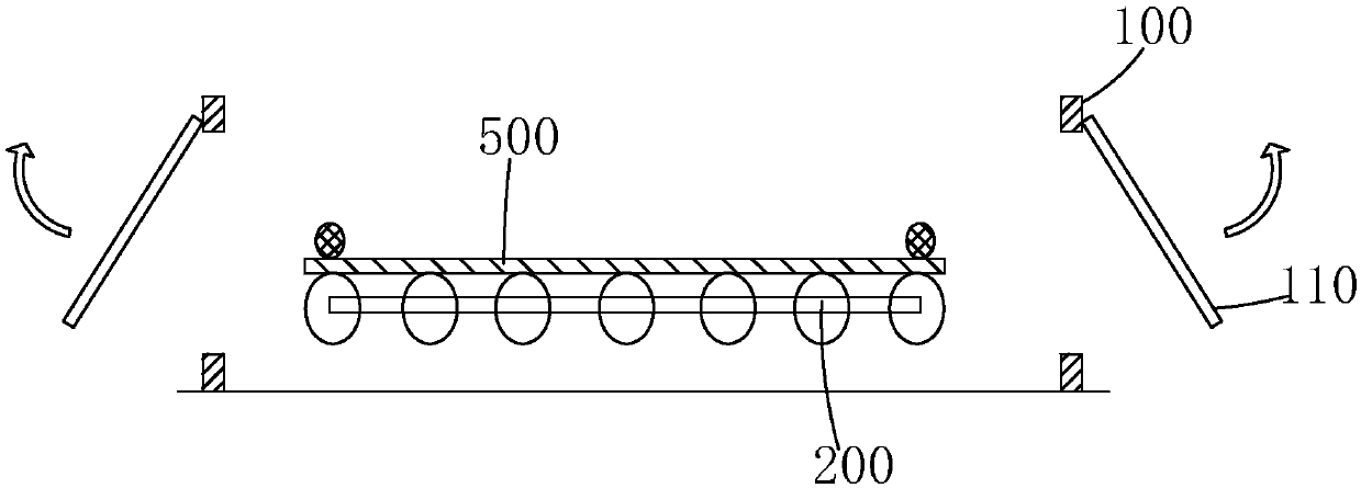
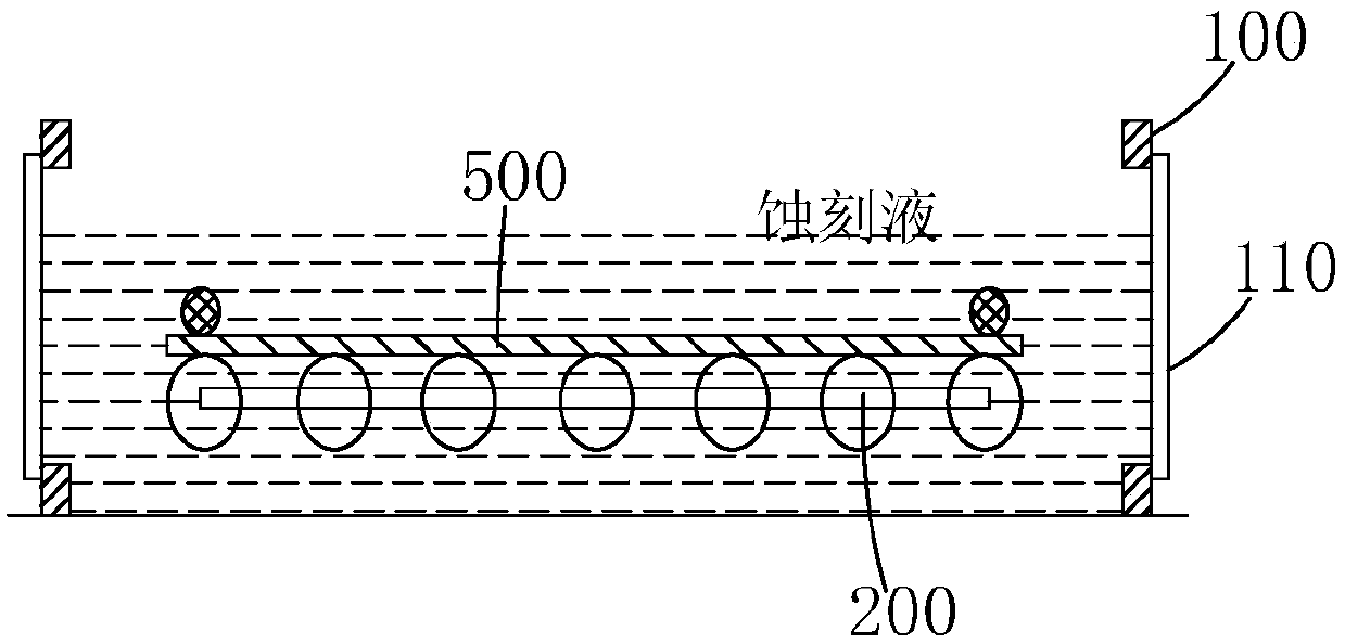
[0008] Then adopt the existing immersion type etching equipment to etch the glass substrate and there will be the following problems: one is for each piece of glass substrate, it is necessary to perform the closing Shutter action and the opening Shutter action to complete the liquid storage and liquid discharge process respectively, and the etching efficiency is relatively low. Second, when draining, the shutters at both ends of the etching tank are quickly opened, which can easily cause uneven flow of etching liquid on the glass substrate, resulting in the formation of mura on the product; third, the existing immersion etching equipment has no standard etching End point judgment unit, the etching end point is generally judged by human eye observation, so the judgment result is very inaccurate

Method used


Image

  • Dip-mode etching device and dip-mode etching method
  • Dip-mode etching device and dip-mode etching method
  • Dip-mode etching device and dip-mode etching method

Examples


Embodiment Construction

[0037] In order to further illustrate the technical means and effects adopted by the present invention, the following describes in detail in conjunction with the embodiments of the present invention and the accompanying drawings.

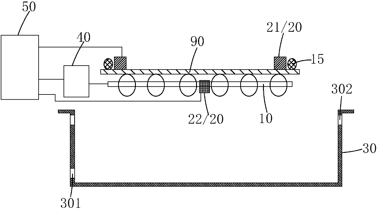
[0038] see image 3 , the present invention provides an immersion etching equipment, comprising a carrier 10 for carrying a substrate 90, a sensor 20 arranged on the carrier 10 and used to determine the end point of etching, and a sensor 20 arranged under the carrier 10 for An etching tank 30 for containing the etching solution and the substrate 90;

[0039] The lower end of the etching tank 30 is provided with a plurality of liquid inlets 301 for delivering the etching solution in the etching tank 30, and the upper end of the etching tank 30 is provided with a plurality of drains for discharging the excess etching solution in the etching tank 30. Liquid port 302;

[0040] The carrying table 10 can move vertically and horizontally, and the carryin...


PUM


Abstract

The invention provides a dip-mode etching device and a dip-mode etching method. The dip-mode etching device includes a bearing platform, a sensor, and an etching groove. The etching groove is providedwith a plurality of liquid inlets and a plurality of liquid outlets at the lower and upper ends respectively. Etching solution is constantly transferred via the liquid inlets, and excessive etching solution is constantly discharged via the liquid outlets, so that there is always etching solution in the etching groove, and the etching solution in the etching groove is always fresh. There is no need to store and discharge etching solution again for each substrate, and the etching efficiency is improved. As the liquid outlets are arranged at the upper end of the etching groove to constantly discharge excessive etching solution, the formation of product Mura due to quick opening of the shutter during liquid discharge of the existing etching device is avoided. In addition, the sensor for judging the end point of etching is set, and compared with observation through eyes, the end point of etching can be judged more accurately, and the best product parameter specification can be obtained.

Description

technical field [0001] The invention relates to the field of manufacturing processes of flat panel displays, in particular to an immersion etching device and an immersion etching method. Background technique [0002] In the field of display technology, flat panel display devices such as Liquid Crystal Display (LCD) and Active Matrix Organic Light-Emitting Diode (AMOLED) display have thin body, high image quality, Many advantages such as power saving and no radiation have been widely used, such as mobile phones, personal digital assistants (PDAs), digital cameras, computer screens or notebook screens, etc. [0003] Thin Film Transistor (Thin Film Transistor, TFT) array (Array) substrates are the main components of current LCD devices and AMOLED devices, and are directly related to the development direction of high-performance flat panel display devices. For example, the LCD manufacturing process generally includes: the front-end array process, the middle-end cell (Cell) proc...

Claims


Application Information

Patent Timeline
Patent Type & Authority Applications(China)
IPC IPC(8): H01L21/67H01L21/3213H01L21/66H01L21/77
Inventor 尹易彪
Owner SHENZHEN CHINA STAR OPTOELECTRONICS TECH CO LTD
Learn More