
Rotating conveying device

A technology of rotating feeding and feeding ports, which is applied to instruments, coin-operated equipment for distributing discrete items, and coin-operated equipment for distributing discrete items. The location requirements are too high, etc.

Pending Publication Date: 2018-01-09
山东显柜网络科技有限公司
View PDF9 Cites 4 Cited by
  • Summary
  • Abstract
  • Description
  • Claims
  • Application Information

AI Technical Summary

Problems solved by technology

[0008] The technical problem to be solved by the present invention is to solve the technical problem that the traditional feeding device is limited by the shape, quantity and quality of the goods, and has too high requirements on the location of the goods to be shipped.

Method used


Image

  • Rotating conveying device
  • Rotating conveying device

Examples


Embodiment Construction

[0024] The following examples are only examples for clarifying the present invention, rather than limiting the embodiment of the present invention. For those of ordinary skill in the art, on the basis of the following descriptions, other different forms of changes or changes can also be made, and these obvious changes or changes that belong to the spirit of the present invention are still within the protection scope of the present invention middle.

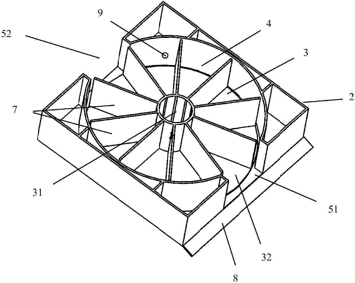
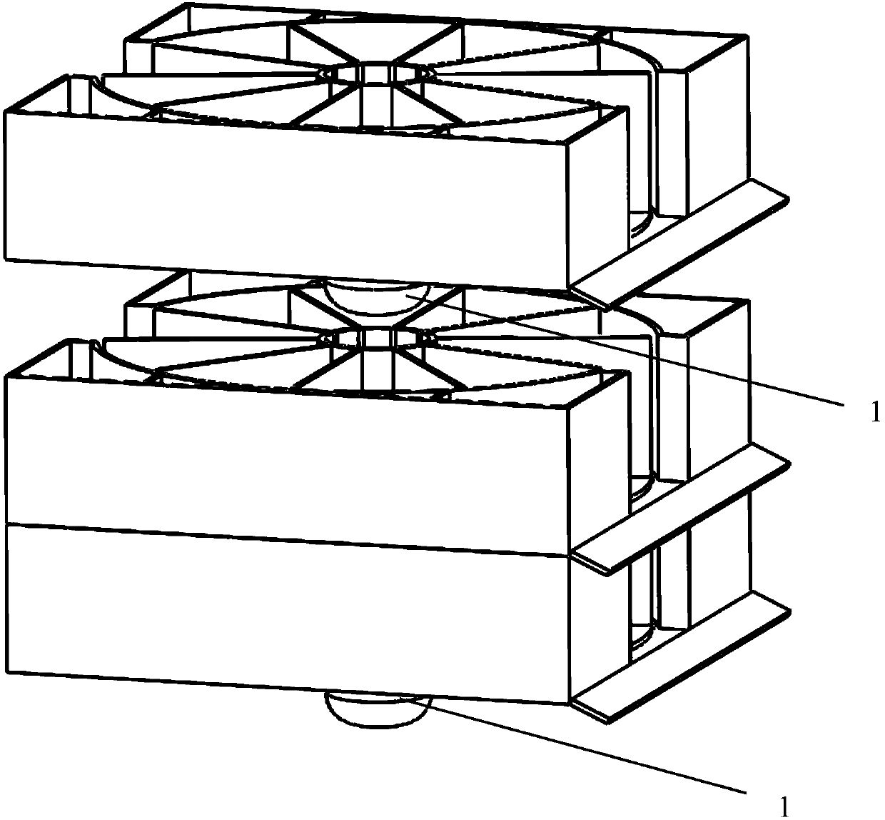
[0025] Such as Figure 1-2 As shown, a rotary feeding device includes a motor 1, and it also includes an outer frame 2 and a split rotating wheel 3. The center of the outer frame 2 is a vertically arranged cylindrical cavity 4, which is located in the cylindrical cavity 4 The front and rear directions of the front and rear direction are respectively provided with feed ports, and the feed ports communicate with the interior of the cylindrical cavity 4, and the split rotating wheel 3 is coaxially sleeved in the cylindrical cavity 4...


PUM


Abstract

The invention relates to a rotating conveying device. The rotating conveying device comprises a motor, an outer frame and a diving and rotating wheel disc; a cylindrical cavity is longitudinally formed in the center of the outer frame, and feed ports are formed in the front and back direction of the cylindrical cavity and are communicated with the inside of the cylindrical cavity; the dividing androtating wheel disc is coaxially sleeved with the cylindrical cavity, a concentric shaft is located in the center of the dividing and rotating wheel disc, and blades are arranged in the radial circumference of the concentric shaft and divide the cylindrical cavity into multiple independent spaces; a motor drives the dividing and rotating wheel disc to axially rotate around the concentric shaft tofeed goods. The independent spaces divided by the blades are used for conveying the goods different in shape, size and quality. The technical problem that a traditional conveying device is limited bythe shape, size and quality of the goods, and the requirement for goods inlet and outlet position is too high is solved.

Description

technical field [0001] The invention relates to a rotary feeding device. Background technique [0002] At present, the feeding devices used in traditional vending machines are roughly divided into the following types: [0003] General snake-shaped stacking feeding device: suitable for cylindrical and cuboid products, which are shipped by their own gravity and rolling. [0004] Disadvantages: Because the goods are cylindrical or cuboid, the number of varieties is limited to a certain extent. In addition, the quality and bearing capacity of the goods must be considered in the stacking method. For non-cylindrical and cuboid goods, it is necessary to add a cylinder outside the goods, which increases the cost. [0005] Spring tray drawer-type push feeding device: suitable for small products of various rules, which are pushed out by the motor rotating the coil spring. [0006] Disadvantages: The number of added products is limited by the length of the feeding device, which cann...

Claims


Application Information

Patent Timeline
Patent Type & Authority Applications(China)
IPC IPC(8): G07F11/24
Inventor 徐天
Owner 山东显柜网络科技有限公司
Learn More