Hydraulic Synchronization Valve

A hydraulic synchronization, solenoid valve technology, applied in the direction of fluid pressure actuating devices, servo motor components, mechanical equipment, etc., can solve the problem of increasing the burden and instability of the hydraulic system, high requirements on the strength of the hydraulic system, and reducing the stability of the hydraulic system. and other issues, to achieve the effect of improving the applicable scope, low cost and ensuring safety.

Inactive Publication Date: 2019-04-19
广东德奥电梯科技有限公司
View PDF5 Cites 0 Cited by
  • Summary
  • Abstract
  • Description
  • Claims
  • Application Information

AI Technical Summary

Problems solved by technology

[0002] In the hydraulic system, if you want to make multiple actuators run synchronously, it is usually realized by computer control, or by using multi-stage shunt of hydraulic pipelines. However, these implementation methods not only have low control accuracy, but also lead to the complexity of the hydraulic system. In addition, when there are multiple actuators, the oil intake and oil discharge of the actuators are usually large, and the oil intake and oil discharge of the actuators in the hydraulic system at this stage are usually It is all done at one time, which often requires a large-capacity oil supply and discharge mechanism to match the actuator, which not only increases the volume of the hydraulic system, increases the cost of the hydraulic system, but also requires high strength of the hydraulic system, and increases the The burden and instability of the hydraulic system, there is a greater safety hazard

Method used


Image

  • Hydraulic Synchronization Valve
  • Hydraulic Synchronization Valve

Examples


Embodiment Construction

[0015] The present invention will be described in further detail below in conjunction with the accompanying drawings.

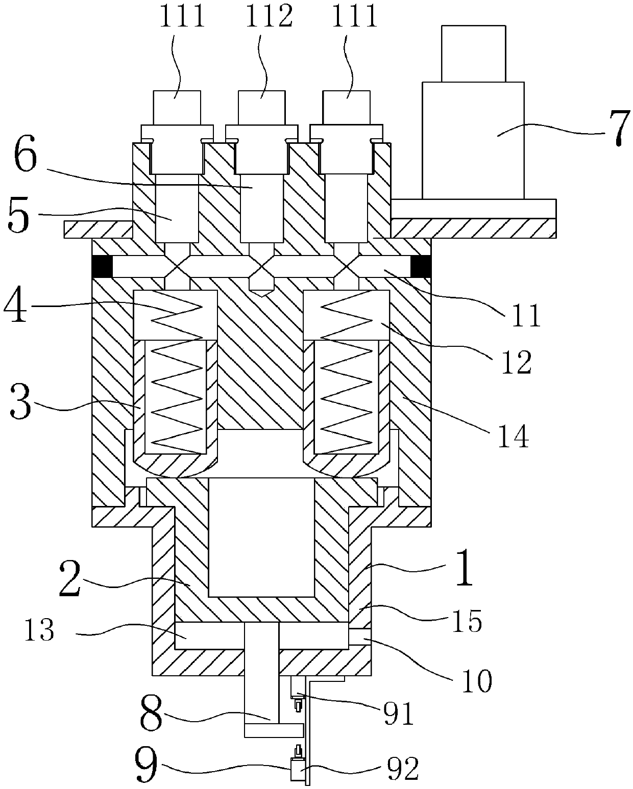
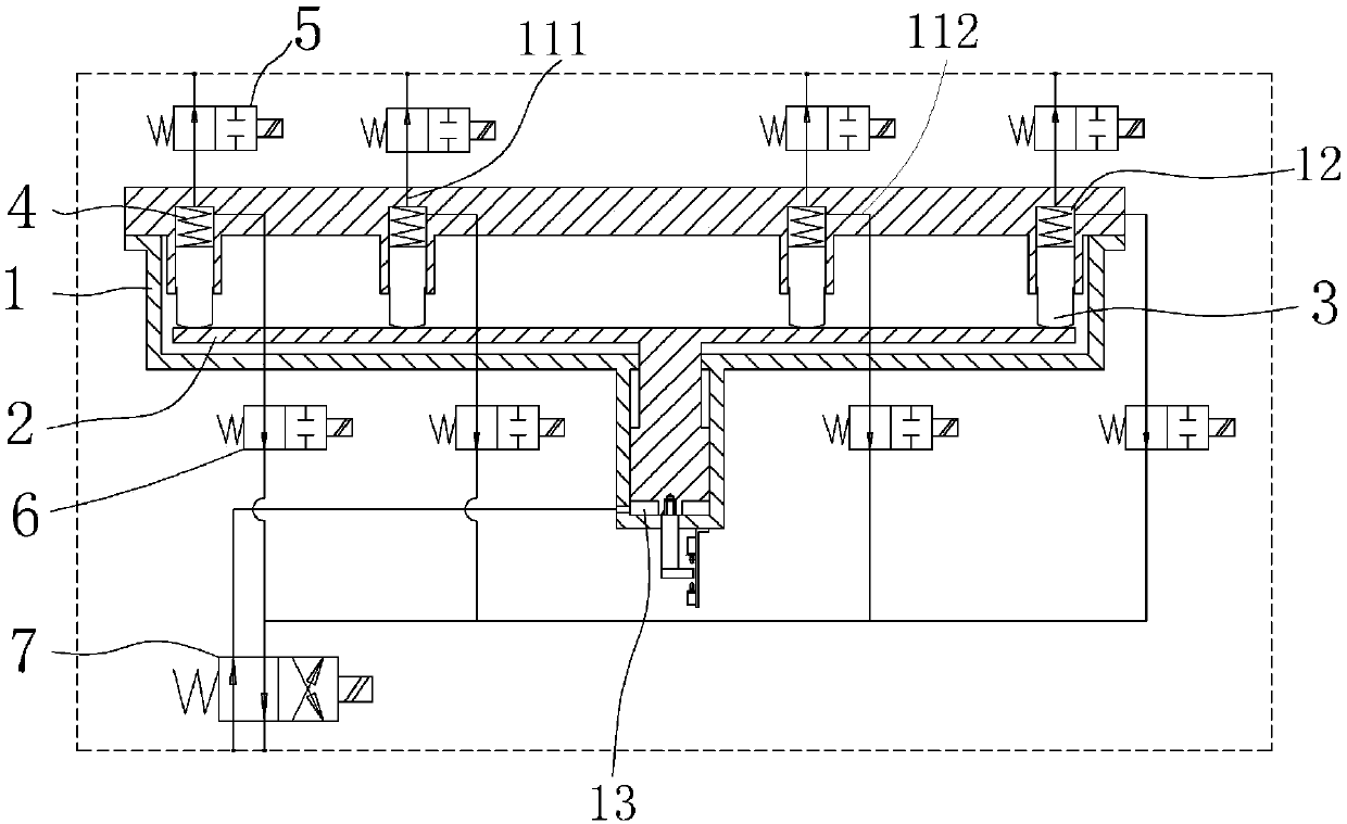
[0016] refer to figure 1 and figure 2 , The hydraulic synchronous valve of the present invention includes a cylinder 1, a main plunger 2, a sub-plunger 3, a spring 4, a first solenoid valve 5, a second solenoid valve 6, a push rod 8 and an induction switch 9.

[0017] The cylinder block 1 includes a cylinder body 14 and a cylinder head 15, the cylinder body 14 and the cylinder head 15 are connected by bolts, the cylinder body 14 is provided with an oil passage 11, and the oil passage 11 includes a working oil passage 111 and an oil return passage 112.

[0018] The size of the main plunger 2 matches the cylinder head 15, and the main plunger 2 is embedded in the cylinder head 15, so that the main plunger 2 and the cylinder head 15 enclose a second cavity 13, and the cylinder head 15 is provided with an oil port 10 , the oil port 10 communicates with the sec...


PUM


Abstract

The invention discloses a hydraulic synchronous valve which comprises a cylinder block, a primary plunger piston, a plurality of secondary plunger pistons, springs, a first solenoid valve, a second solenoid valve, an ejector rod and an inductive switch. An oil channel is formed in the cylinder block. The secondary plunger pistons are positioned in the cylinder block. First cavities are defined bythe secondary plunger pistons and the cylinder block. The first oil cavities communicate with the oil channel. The oil channel comprises a working oil channel and an oil return channel. The first solenoid valve is connected with the working oil channel. The second solenoid valve is connected with the oil return channel. The primary plunger piston is mounted in the cylinder block. A second cavity is defined by the primary plunger piston and the cylinder block. The primary plunger piston is in contact with the secondary plunger pistons. One end of each spring is connected with the correspondingsecondary plunger piston and the other end of the spring is connected with the cylinder block. The ejector rod is connected with the primary plunger piston. The inductive switch is mounted on the cylinder block, and is matched with the ejector rod. The inductive switch is electrically connected with the first solenoid valve and the second solenoid valve. Therefore, synchronous work of a pluralityof executing components and stepped oil discharging or stepped oil feeding of the executing components can be simply achieved, the control precision is high, the cost is low, the stability is high, and the safety is high.

Description

technical field [0001] The invention relates to the design of hydraulic components, in particular to a hydraulic synchronous valve. Background technique [0002] In the hydraulic system, if you want to make multiple actuators run synchronously, it is usually realized by computer control, or by using multi-stage shunt of hydraulic pipelines. However, these implementation methods not only have low control accuracy, but also lead to the complexity of the hydraulic system. In addition, when there are multiple actuators, the oil intake and oil discharge of the actuators are usually large, and the oil intake and oil discharge of the actuators in the hydraulic system at this stage are usually It is all done at one time, which often requires a large-capacity oil supply and discharge mechanism to match the actuator, which not only increases the volume of the hydraulic system, increases the cost of the hydraulic system, but also requires high strength of the hydraulic system, and incr...

Claims


Application Information

Patent Timeline
Patent Type & Authority Patents(China)
IPC IPC(8): F15B13/08
Inventor 吴家集黄伟赵恒
Owner 广东德奥电梯科技有限公司
Why Eureka
Try Eureka