Eureka AIR delivers breakthrough ideas for toughest innovation challenges, trusted by R&D personnel around the world.

Handheld minimally-invasive surgical instrument with self-locking function

A minimally invasive surgery, hand-held technology, used in surgery, medical science and other directions, can solve the problems of low flexibility, lack of self-locking, inconvenient operation, etc. Effect

Active Publication Date: 2018-01-09
JILIN UNIV
View PDF17 Cites 11 Cited by
  • Summary
  • Abstract
  • Description
  • Claims
  • Application Information

AI Technical Summary

Problems solved by technology

[0004] The present invention aims to solve the problems that the existing hand-held minimally invasive surgical instruments are inconvenient to operate and have low flexibility, and the mechanism that drives the end effector to realize the degree of freedom of rotation and deflection does not have self-locking property, and further proposes a self-locking machine Hand-held minimally invasive surgical instrument; the driving device of the self-locking handheld minimally invasive surgical instrument to realize the rotation and deflection movement is self-locking, allowing the end effector to perform surgery in any posture in the limited surgical space Operation, through the reasonable layout of the rope transmission, has no coupling movement; the self-locking hand-held minimally invasive surgical instrument will not produce force on the patient's wound during the operation

Method used


Image

  • Handheld minimally-invasive surgical instrument with self-locking function
  • Handheld minimally-invasive surgical instrument with self-locking function
  • Handheld minimally-invasive surgical instrument with self-locking function

Examples


Embodiment Construction

[0038] The technical solution of the present invention will be further described below in conjunction with the accompanying drawings and specific embodiments:

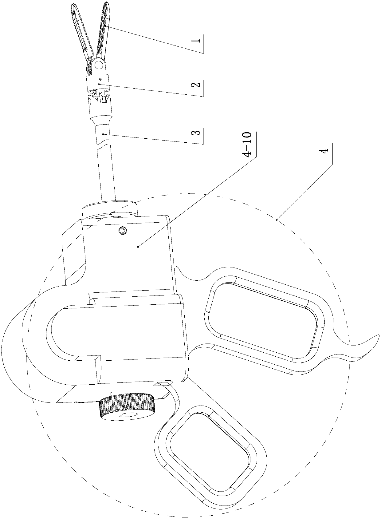
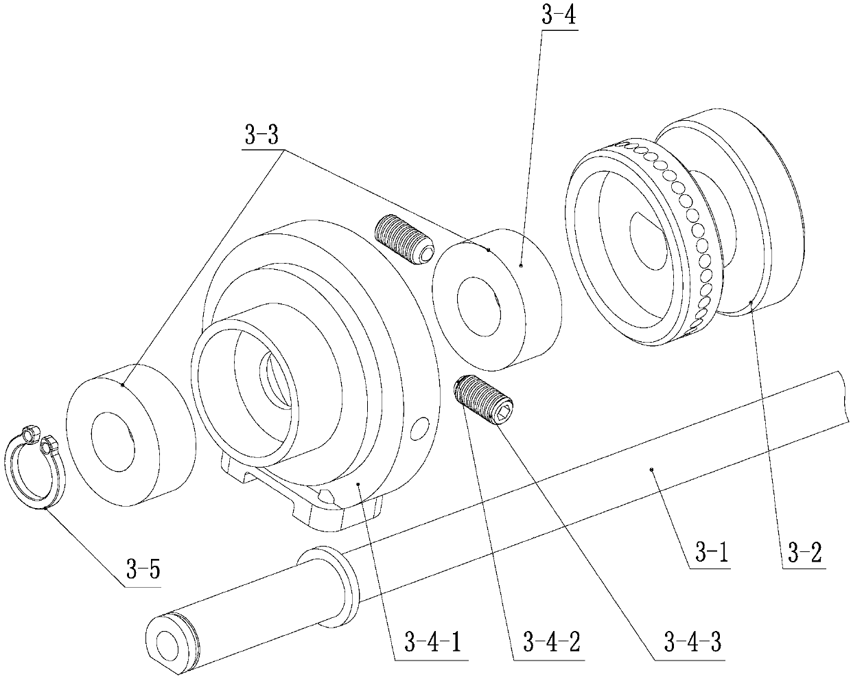
[0039] see Figure 1-Figure 12 Explain that a self-locking hand-held minimally invasive surgical instrument includes an end effector 1, an end wrist joint 2, an end effector operating device 3 and a handle operating device 4;

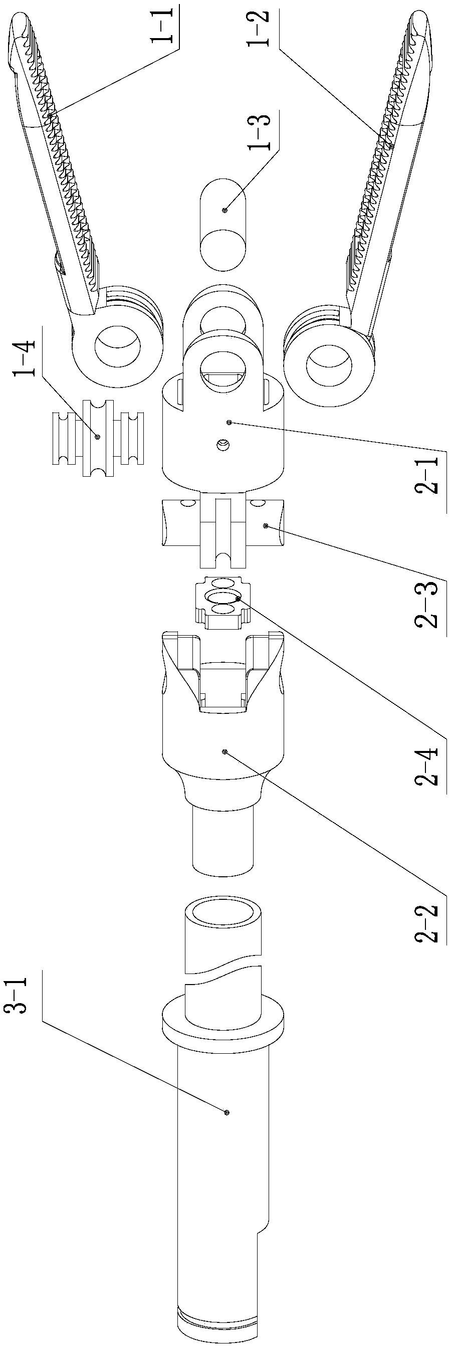
[0040]The terminal wrist joint 2 includes a wrist rotation joint 2-1, a wrist connector 2-2, a joint rotation shaft 2-3 and a rope guide block 2-4; the wrist rotation joint 2-1 passes through the joint rotation shaft 2 -3 is rotationally connected with the wrist connector 2-2, and the rope guide block 2-4 is connected with the wrist connector 2-2;

[0041] The end effector 1 includes two terminal fingers 1-1, an opening and closing rotation shaft 1-3 and a rope guide wheel 1-4; the opening and closing rotation shaft 1-3 is installed on the wrist rotation joint 2-1, two The terminal finger 1-1 ...


PUM


Abstract

The invention relates to the technical field of thoracic and abdominal minimally-invasive surgical medical equipment, in particular to a handheld minimally-invasive surgical instrument with a self-locking function, and is intended to solve the problems that an existing handheld minimally-invasive surgical instrument is inconvenient to operate and low in flexibility, and a mechanism driving an endeffector to gain rotation and deflection degrees of freedom has no self-locking function. The handheld minimally-invasive surgical instrument comprises an end effector, an end wrist joint, an end effector operating device and a handle operating device; the end wrist joint includes a wrist rotary joint, a wrist connector, a joint rotary shaft and a rope guide block; the rope guide block is connected with the wrist connector; the handle operating device includes a fixing handle, an opening-closing control handle, a handle rotary shaft, a deflecting control device, a guide wheel post unit, a shell and a support plate; the opening-closing control handle is rotationally connected with the fixing handle through the handle rotary shaft, the guide wheel post unit is disposed between the deflectingcontrol device and a spring-ball self-rotating locking device, and the guide wheel post unit, the deflecting control device and the spring-ball self-rotating locking device are mounted on the upper surface of the support plate. The handheld minimally-invasive surgical instrument is applicable to thoracic and abdominal minimally-invasive surgeries.

Description

technical field [0001] The invention relates to the technical field of thoracoabdominal cavity minimally invasive surgery medical equipment, in particular to a hand-held surgical instrument with self-locking property, which assists an assistant in pulling tissue. Background technique [0002] Minimally Invasive Surgery (MIS) represented by laparoscopy is known as one of the important contributions of medical science to human civilization in the 20th century. Its application makes some surgical operations bid farewell to the traditional open surgery mode. Minimally invasive surgery means that the surgeon cuts 2-4 small incisions of 5-10mm on the patient's body surface, inserts surgical instruments into the human body through the patient's tiny incisions, and uses visual monitoring equipment and dexterous surgical instruments to treat the lesion. site for diagnosis or treatment. Surgical instruments, as the execution tools in the minimally invasive surgery process, directly i...

Claims


Application Information

Patent Timeline
Patent Type & Authority Applications(China)
IPC IPC(8): A61B17/02A61B17/00
Inventor 冯美张海军李秋萌郝良天
Owner JILIN UNIV
Why Eureka
Eureka Blog
Learn More