Mobile terminal sharing radio frequency antenna

A technology for radio frequency antennas and mobile terminals, which is applied to antennas, antenna parts, and devices that enable antennas to work in different bands at the same time, and can solve the problems of interference and high cost of radio frequency modules and distance sensing modules, and achieve cost savings and quantity reduction Effect

Active Publication Date: 2018-01-05
河北上博电气制造有限公司
View PDF7 Cites 5 Cited by
  • Summary
  • Abstract
  • Description
  • Claims
  • Application Information

AI Technical Summary

Problems solved by technology

[0006] In view of the shortcomings of the above-mentioned prior art, the purpose of the present invention is to provide a mobile terminal that shares a radio frequency antenna, aiming to solve the problems of serious interference and high cost of radio frequency modules and distance sensing modules in existing mobile devices

Method used


Image

  • Mobile terminal sharing radio frequency antenna
  • Mobile terminal sharing radio frequency antenna
  • Mobile terminal sharing radio frequency antenna

Examples


Embodiment Construction

[0021] The present invention provides a mobile terminal that shares a radio frequency antenna. In order to make the purpose, technical solution and effect of the present invention more clear and definite, the present invention will be further described in detail below with reference to the accompanying drawings and examples. It should be understood that the specific embodiments described here are only used to explain the present invention, not to limit the present invention.

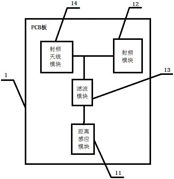
[0022] like figure 2 As shown, a structural block diagram of a mobile terminal sharing a radio frequency antenna provided by the present invention includes a PCB board 1 on which a distance sensing module 11, a radio frequency module 12, a filtering module 13 and a radio frequency antenna module 14 are arranged. The distance sensing module 11 is connected to the radio frequency antenna module 14 through the filter module 13 , and the radio frequency antenna module 14 is also connected to the radio frequ...


PUM


Abstract

The invention discloses a mobile terminal sharing a radio frequency antenna. The mobile terminal comprises a printed circuit board (PCB), wherein the PCB is provided with a distance sensing module, aradio frequency module, a filter module that is used to block signals required for the operation of a non-distance sensing module, and a radio frequency antenna module that is used to produce a resonant frequency required for the operation of the distance sensing module and the resonant frequency required for the operation of the radio frequency module, the distance sensing module is connected with the radio frequency antenna module through the filter module, and the radio frequency antenna module is also connected with the radio frequency module. According to the mobile terminal disclosed bythe invention, the radio frequency antenna module that can produce high-frequency and low-frequency resonant frequencies and the filter module are adopted, and thus the distance sensing module and theradio frequency module can share one antenna without affecting each other, the radio frequency performance and distance sensing effect can be simultaneously met by sharing one antenna, and the problem that serious mutual interference is caused as two antennae are close to each other and are both made of metal materials in existing technologies can be solved.

Description

technical field [0001] The invention relates to the field of antenna design of a mobile terminal with a distance sensing function, in particular to a mobile terminal sharing a radio frequency antenna. Background technique [0002] With the development of communication technology, mobile communication products such as mobile phones have become indispensable equipment for people. At present, more and more mobile phones have a distance sensing function. [0003] The distance sensing function can reduce the radiation of the mobile terminal to the human body, and can also save the power of the mobile terminal. When the human body is close to the mobile terminal, the transmission function of the antenna is reduced, thereby reducing the radiation of the antenna to the human body. Therefore, most mobile terminals currently Both are equipped with distance sensing function. [0004] The distance sensing chip and radio frequency chip of existing products are separately connected to t...

Claims


Application Information

Patent Timeline
Patent Type & Authority Applications(China)
IPC IPC(8): H04B1/40H04B1/18
CPCH01Q1/243H01Q1/245H04B1/0057H04B1/0458H04B1/18H04B1/3838H01Q5/50H04B1/40
Inventor 徐健华黄帆
Owner 河北上博电气制造有限公司
Why Eureka
Try Eureka