
Winding tool of stator coil

A winding tool and stator coil technology, which is applied in the manufacture of motor generators, electrical components, electromechanical devices, etc., can solve the problem of lack of simple and convenient winding tools for small motor coils, and achieve the effect of simple structure and high winding efficiency

Inactive Publication Date: 2018-01-05
ANHUI JINWAN PUMP TECH CO LTD
View PDF3 Cites 3 Cited by
  • Summary
  • Abstract
  • Description
  • Claims
  • Application Information

AI Technical Summary

Problems solved by technology

[0003] The purpose of the present invention is to solve the defect in the prior art that there is no simple and convenient coil winding tool suitable for small motor manufacturers, and to provide a winding tool for stator coils to solve the above problems

Method used

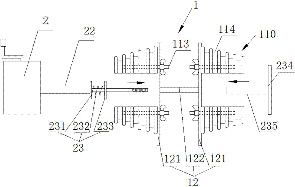
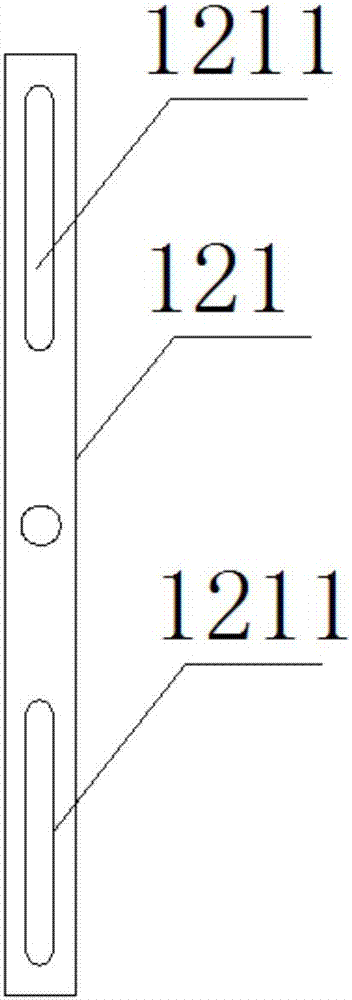
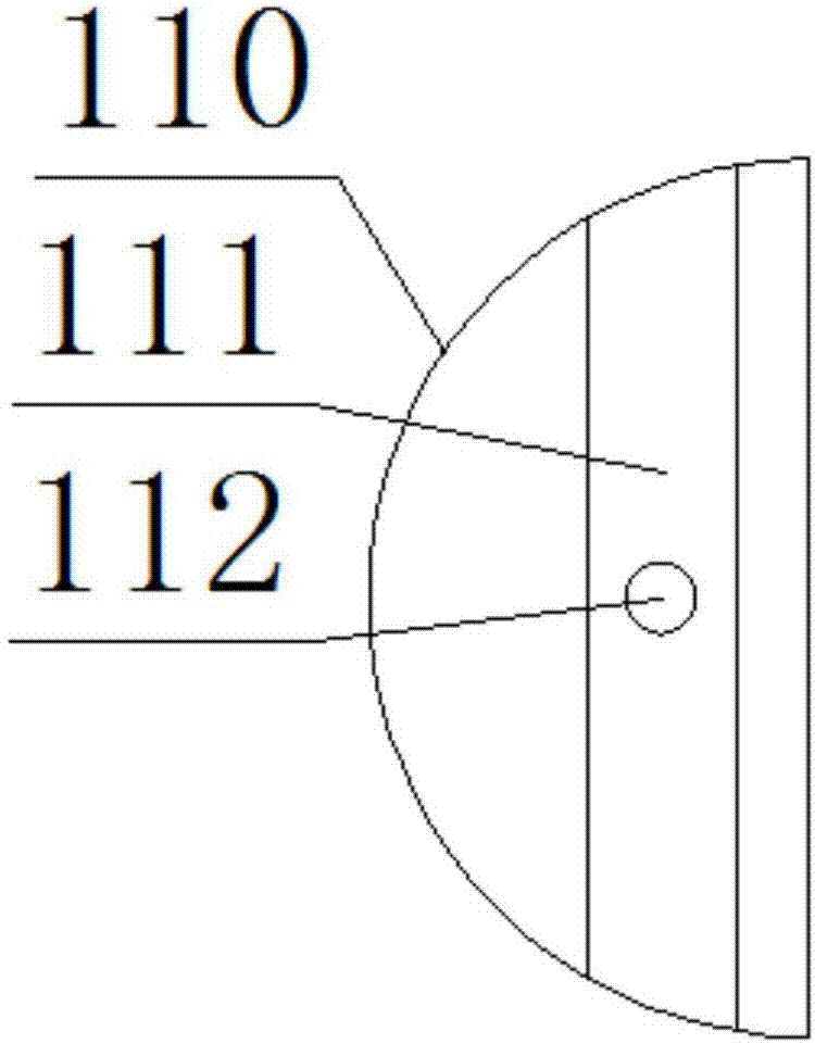

Image

  • Winding tool of stator coil
  • Winding tool of stator coil
  • Winding tool of stator coil

Examples


Embodiment Construction

[0026] In order to have a further understanding and understanding of the structural features of the present invention and the achieved effects, the preferred embodiments and accompanying drawings are used for a detailed description, as follows:

[0027] Such as figure 1 , figure 2 , image 3 As shown, a winding tool for a stator coil includes a winding mechanism 1, a driving mechanism 2, and a counter; the driving mechanism 2 drives the winding mechanism 1 to rotate;

[0028] The driving mechanism 2 is a hand-operated winding machine; the hand-operated winding machine includes a crank; the crank is linked with the drive shaft 22 . The counter is used to count the number of turns of the winding section. How to realize the counting function of the counter, as well as its circuit structure, and the assembly structure of the hand-operated winding machine are all prior art, and will not be described in detail here.

[0029] The winding mechanism 1 includes a winding part 11 an...


PUM


Abstract

The invention provides a winding tool of a stator coil. The winding tool comprises a winding mechanism, a driving mechanism and a counter. The driving mechanism drives the winding mechanism to rotate.The winding mechanism comprises a winding portion and a fixing seat. The winding portion comprises two winding sub-portions. The two winding sub-portions are oppositely arranged and are fixed to thefixing seat in a sliding mode, so that the two winding sub-portions perform relative motions to achieve the coil diameter adjusting purpose. The winding portion is provided with multiple notches for limiting copper wires. The counter is used for calculating the turn number of the winding portion. Compared with the prior art, the winding tool is simple in structure and high in winding efficiency. By arranging the winding portion into the two winding sub-portions capable of performing relative motions, the same winding portion can be used for winding different diameters of coils, and the complicated work of dismounting and replacing the winding portion is avoided.

Description

technical field [0001] The invention relates to the technical field of stator coils, in particular to a winding tool for stator coils. Background technique [0002] The winding technology of the electronic coil directly affects the performance of the motor. In the existing technology, the winding technology of the coil is either manual winding or a fully automatic winding machine with a very complicated structure. However, for some small manufacturers, manual winding has low productivity and low precision, while large-scale winding machines have high costs, and small manufacturers have limited funds and insufficient purchasing capacity. Therefore, there is an urgent need for a small coil winding machine with high winding precision, low cost and convenient operation to meet the urgent needs of small manufacturers. Contents of the invention [0003] The purpose of the present invention is to solve the defect in the prior art that there is no simple and convenient coil windi...

Claims


Application Information

Patent Timeline
IPC IPC(8): H02K15/04
Inventor 余雷
Owner ANHUI JINWAN PUMP TECH CO LTD
Learn More