Eureka AIR delivers breakthrough ideas for toughest innovation challenges, trusted by R&D personnel around the world.

High-precision large-dynamic range measurement system and measurement method for transmission element aberration

A large dynamic range, transmission element technology, applied in the field of measurement, can solve problems such as small dynamic range, expensive measurement equipment, and complicated measurement process, and achieve the effects of simplified calibration, reduced difficulty in system construction and use, and simple operation

Inactive Publication Date: 2018-01-05
CHINA JILIANG UNIV
View PDF6 Cites 10 Cited by
  • Summary
  • Abstract
  • Description
  • Claims
  • Application Information

AI Technical Summary

Problems solved by technology

[0003] In order to solve the technical problems of the non-contact high-precision transmission element surface detection in the prior art, the dynamic range is small, the measurement process is complicated, and the measurement equipment is expensive. Transmission element aberration detection system and measurement method with high precision and large dynamic range

Method used


Image

  • High-precision large-dynamic range measurement system and measurement method for transmission element aberration
  • High-precision large-dynamic range measurement system and measurement method for transmission element aberration
  • High-precision large-dynamic range measurement system and measurement method for transmission element aberration

Examples


Embodiment 1

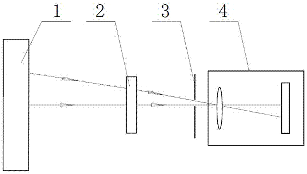
[0018] Such as figure 1 As shown, a high-precision and large dynamic range measurement system for the aberration of a transmission element includes a display 1, a transmission element to be measured 2, a filter aperture plate 3, a CCD camera 4, a coordinate measuring machine (not shown) and computer (not shown). attached figure 1 It is a schematic diagram of the optical path of the optical deflection measurement of the present invention, and the thin solid line with arrows in the figure indicates the direction of the optical path. The transmission element 2 to be measured is a measured object through which light with processing errors can pass through the element body. The CCD camera 4 is an industrial camera. The display screen of the display 1 is arranged face to face with the lens of the CCD camera 4 . The central axis of the lens of the CCD camera 4 is perpendicular to the display screen of the display 1 and is located at the center of the display screen. The transmis...


PUM

PropertyMeasurementUnit
Diameteraaaaaaaaaa
Diagonal lengthaaaaaaaaaa

Abstract

The invention provides a high-precision large-dynamic range measurement system and a measurement method for transmission element aberration, which relate to the technical field of measurement. A three-coordinate measuring machine is used for pre-calibrating structural position parameters of the measurement system, a to-be-measured transmission element is placed between a display screen and a CCD camera, a four-step phase-measuring method is adopted to solve phase distribution corresponding to stripes, the actual spot coordinate value of a point on the transmission surface of the to-be-measuredtransmission element corresponding to the phase projected on the CCD camera is obtained, a ray tracing method is then used to generate an ideal coordinate value based on structural position parameters of a detection optical path, slope error calculation is carried out on the to-be-measured transmission element on the basis, and finally, an integral method is used to obtain element aberration data. The technical problems of small dynamic range and expensive equipment for non-contact high-precision transmission element surface detection in the prior art can be solved, a universal feasible method is provided for large-dynamic range transmission element aberration measurement, and an extremely important practical application value is realized.

Description

technical field [0001] The invention relates to the field of measurement technology, in particular to a system and a measurement method for measuring the aberration of a transmission element based on optical deflection. Background technique [0002] Transmission components are indispensable in optical components and industrial products. It is widely used in imaging optics, illumination optics, transmission glass and clear glass. With the development of industrial production and the advancement of scientific research and technology, the requirements for the detection of processing errors of transmission elements are also continuously increasing. The current detection methods mainly include: interferometry and geometric light detection. Interferometry, as a sub-wavelength optical measurement method, has been widely used. Common interferometers such as Fizeau interferometer, Tieman Green interferometer and point diffraction interferometer provide a non-contact high-precision...

Claims


Application Information

Patent Timeline
IPC IPC(8): G01M11/02
Inventor 王道档徐平解钟敏龚志东孔明刘维赵军郭天太
Owner CHINA JILIANG UNIV
Why Eureka
Eureka Blog
Learn More