
Vehicle periphery monitoring system

A monitoring system and vehicle technology, applied in the field of vehicles, can solve the problems of easily damaged and damaged cameras, and achieve the effects of reducing the risk of easy damage, protecting the lens from dust and water, and enhancing the support strength

Inactive Publication Date: 2018-01-05
NANJING WEILI INNOVATIVE ENERGY TECH CO LTD
View PDF0 Cites 4 Cited by
  • Summary
  • Abstract
  • Description
  • Claims
  • Application Information

AI Technical Summary

Problems solved by technology

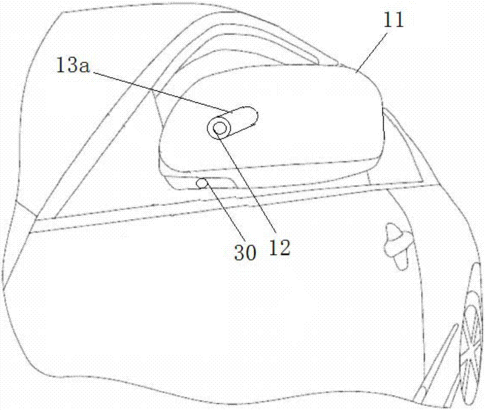
The camera set above or below the rearview mirror is part of it. We have seen in reality that such cameras are usually set at the edge of the rearview mirror. The cameras designed up and down are in a dangerous situation and are easily dropped by the external environment. Injury situations, such as accidental rubbing, friction and falling objects from outside, etc. Compared with the rearview mirror, the camera designed in this way is easier to be damaged and damaged

Method used


Image

  • Vehicle periphery monitoring system
  • Vehicle periphery monitoring system
  • Vehicle periphery monitoring system

Examples


Embodiment Construction

[0031] In order to better understand the technical content of the present invention, specific embodiments are given together with the attached drawings for description as follows.

[0032] Aspects of the invention are described in this disclosure with reference to the accompanying drawings, which show a number of illustrated embodiments. Embodiments of the present disclosure are not necessarily intended to include all aspects of the invention. It should be appreciated that the various concepts and embodiments described above, as well as those described in more detail below, can be implemented in any of numerous ways, since the concepts and embodiments disclosed herein are not limited to any implementation. In addition, some aspects of the present disclosure may be used alone or in any suitable combination with other aspects of the present disclosure.

[0033] According to the disclosure and improvement of the present invention, a vehicle surrounding monitoring system, especi...


PUM


Abstract

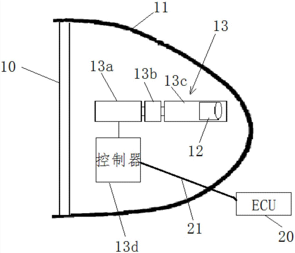
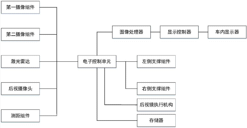
The invention provides a survey system around the vehicle, including reflex mirrors, housing, camera components, and support components, which are symmetrical design on the left and right sides of the vehicle.It also includes laser radar, first camera components, second camera components, rear view cameras, and ranging components. They are connected to electronic control units through the vehicle bus to data transmission and control instruction transmission.The reflective mirror, shell, camera component, and support component constitute an integrated rearview mirror system on one side. The survey system around the entire vehicle includes the integrated rearview mirror system on the left and right sides.The support component is used to support the camera component and control the motor motion when the vehicle starts to drive the camera component to extend the shell, and control the motor motion when the vehicle is turned off to drive the camera component into the shell.

Description

technical field [0001] The invention relates to the technical field of vehicles, in particular to a monitoring system around a vehicle and a vehicle. Background technique [0002] In the prior art, due to the limitation of the position of the driver in the vehicle and the structure of the frame, there are usually blind spots in front of the driver and in the front direction of the left and right sides. Usually, in order to enhance such a visual observation area, the rear view on both sides of the vehicle can be A camera is installed facing forward on the mirror to monitor the visual area ahead in an enlarged manner. For example, the camera installed above or below the rearview mirror reflects the real-time collected image to the front of the driver in the car through the image transmission bus, and realizes a wider range of observation with the help of the wide-angle design of the camera. [0003] In the existing whole-vehicle bird's-eye view system or 360-degree surveillan...

Claims


Application Information

Patent Timeline
Patent Type & Authority Applications(China)
IPC IPC(8): B60R1/00B60R1/12
Inventor 陈兰陈勇
Owner NANJING WEILI INNOVATIVE ENERGY TECH CO LTD
Learn More