
Automatic locking device for bolt and control method of automatic locking device

A locking device and bolt technology, applied in the direction of manufacturing tools, metal processing, connecting components, etc., can solve the problems of low work efficiency, hidden quality problems, twisted bolts, etc., and achieve the effect of improving locking quality and improving work efficiency.

Pending Publication Date: 2018-01-05
广州市韦德电气机械有限公司
View PDF0 Cites 8 Cited by
  • Summary
  • Abstract
  • Description
  • Claims
  • Application Information

AI Technical Summary

Problems solved by technology

[0003] 1. The speed of the traditional locking bolt machine is fixed. When using a faster locking bolt machine, if the position of the bolt is not correct or the thread on the component is abnormal, and the locking can not be stopped in time for adjustment, it will It will cause the locking bolt to tilt, or even twist the bolt or the bolt will not be locked tightly.
When using a slower locking bolt machine, it will cause low work efficiency;
[0004] 2. In the process of locking the bolts, since the motor is driving the screws to lock, it is difficult for people to feel the strength of the locking bolts during this process, so it is difficult to judge whether the current bolts are locked or slipped. Quality hidden danger

Method used


Image

  • Automatic locking device for bolt and control method of automatic locking device
  • Automatic locking device for bolt and control method of automatic locking device
  • Automatic locking device for bolt and control method of automatic locking device

Examples


Embodiment Construction

[0027] The present invention will be further described below in conjunction with accompanying drawing.

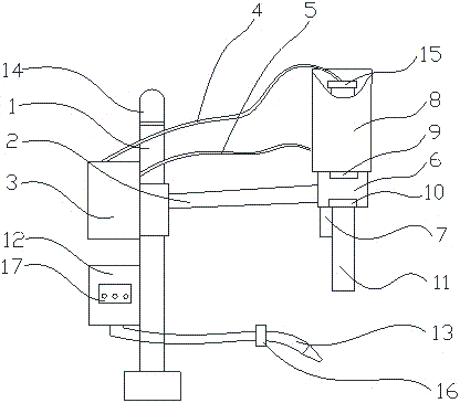
[0028] see figure 1 , the present invention includes a pillar 1, a support arm 2, a servo driver 3, a motor encoder line 4, a motor power line 5, a reducer 6, a position sensor 7, a servo motor 8, a torque sensor 9, a torque sensor 10, and a connector 11, screw thread glue storage 12, thread glue dropper 13 etc. constitute. The servo drive 3 and the thread glue storage 4 are placed on the pillar 1; the speed reducer 6 is connected to the pillar 1 through the support arm 2; the speed reducer 6 is equipped with the Servo motor 8; the servo driver 3 and the servo motor 8 are connected together through the motor encoder line 4 and the motor power line 5; the connector 11 is fixed below the reducer 6, and the The connector 11 can be equipped with a sleeve or a Phillips screwdriver; a position sensor 7 is installed on one side of the reducer 11 to form the whole device.

[002...


PUM


Abstract

The invention provides an automatic locking device for a bolt and a control method of the automatic locking device. The automatic locking device for the bolt comprises a supporting column, a supporting arm, a servo driver, a motor encoder wire, a motor power wire, a speed reducer, a position sensor, a servo motor, torque sensors, a connector, an anaerobic adhesive storage device and an anaerobic adhesive dropper. The control method comprises the following steps that 1, the servo driver is used for slowly driving the servo motor and the speed reducer to accelerate so that the connector can be driven to normally lock the bolt into a part, and the connector rotates at a constant speed; and 2, when the bolt is close to the locking position, the servo motor starts to decelerate, and the servo motor stops rotating when the torque values fed back by the torque sensors reach a set torque value. According to the automatic locking device for the bolt and the control method of the automatic locking device, the position sensor is arranged to judge whether the bolt is installed in place or not and whether the blot is inclined or not; the anaerobic adhesive dropper is arranged so that manual control over the extrusion amount of the anaerobic adhesive can be avoided; and the working efficiency of the locking of the bolt is improved, and the assembling quality is improved.

Description

technical field [0001] The invention relates to the technical field of bolt fastening, and more specifically, relates to an automatic locking device for assembling bolts and a control method thereof. Background technique [0002] The bolted connection between components is a widely used fastening method. This method has the advantages of simple structure, reliable connection, convenient assembly and disassembly, etc., and is applied to various large, medium, small, light and heavy mechanical and electrical equipment. Therefore, the quality of bolt fastening often determines the quality of the product. The common automatic locking screw device currently on the market consists of a rectifier, a brushless DC motor, a reducer, a sleeve or a screwdriver head. Its working principle is that when the 220V AC power supply is connected, the AC current is rectified into DC by the rectifier, and the DC brushless motor is driven to rotate, thereby driving the sleeve or screwdriver on t...

Claims


Application Information

Patent Timeline
IPC IPC(8): B23P19/06F16B11/00
Inventor 王献伟徐东桂林荣峰李文毫
Owner 广州市韦德电气机械有限公司
Learn More