
Buckle assembling device

An assembly device and buckle technology, used in metal processing, metal processing equipment, manufacturing tools, etc., can solve the problems of finger damage and low efficiency of manual assembly, and achieve the effects of continuous transportation, moderate pressure and improved efficiency.

Pending Publication Date: 2018-01-05
ZHEJIANG SUNNY OPTICAL CO LTD
View PDF7 Cites 4 Cited by
  • Summary
  • Abstract
  • Description
  • Claims
  • Application Information

AI Technical Summary

Problems solved by technology

Therefore, when the buckle snaps into the corresponding position on the lens coating fixture, a large force is required, and the operator's fingers will be damaged during the manual assembly process.
At the same time, due to the large output of lenses, the buckles on the lens coating fixture need to be assembled one by one, resulting in low efficiency of manual assembly

Method used


Image

  • Buckle assembling device
  • Buckle assembling device
  • Buckle assembling device

Examples


Embodiment Construction

[0061] In order to more clearly describe the embodiments of the present invention or the technical solutions in the prior art, the following will briefly introduce the drawings that are used in the embodiments. Apparently, the drawings in the following description are only some embodiments of the present invention, and those skilled in the art can also obtain other drawings according to these drawings without creative efforts.

[0062] When describing the embodiments of the present invention, the terms "vertical", "transverse", "upper", "lower", "front", "rear", "left", "right", "vertical", " The orientation or positional relationship expressed by "horizontal", "top", "bottom", "inner" and "outer" is based on the orientation or positional relationship shown in the relevant drawings, which are only for the convenience of describing the present invention and simplifying the description, and It is not to indicate or imply that the device or element referred to must have a particu...


PUM


Abstract

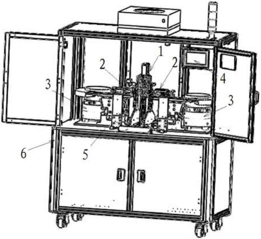
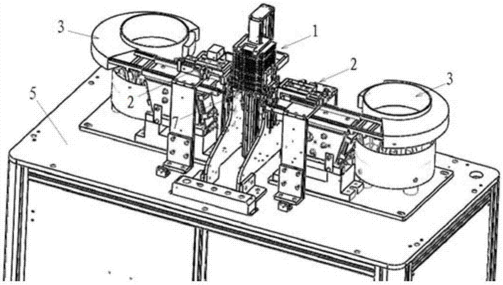
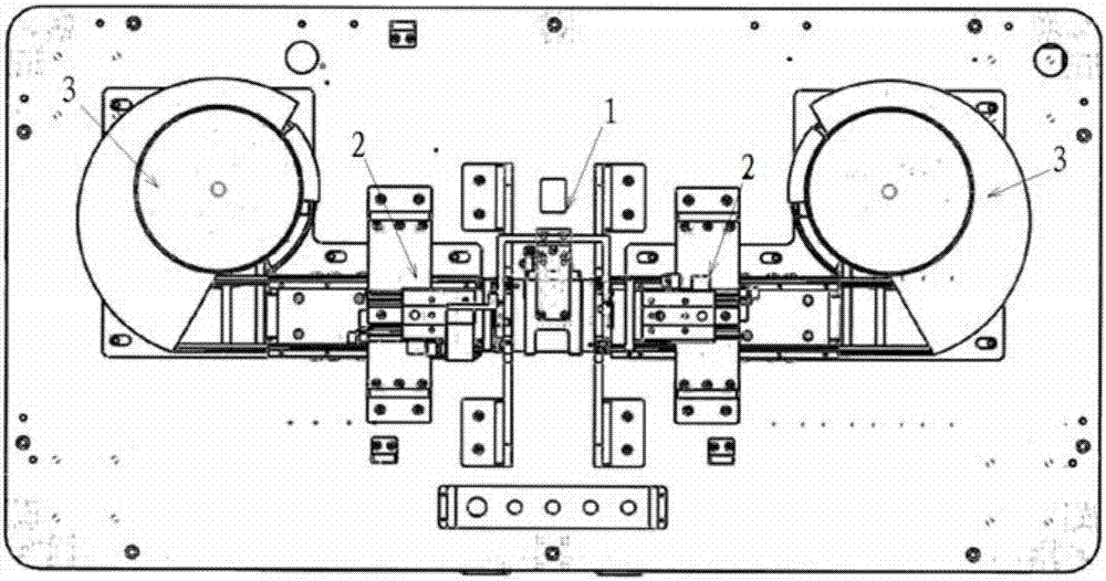
The invention relates to a buckle assembling device. The buckle assembling device comprises a bearing unit (1), assembling units (2), conveying units (3) and a control unit (4). The two assembling units (2) are symmetrically arranged relative to the bearing unit (1). The conveying units (3) correspond to the assembling units (2). The control unit (4) is used for parameter setting and running control. The bearing unit, the assembling units and the conveying units are in a coordinated effect, accordingly real-time and continuous transportation of buckles is achieved, and the buckles can be automatically assembled to clamps. By means of the above arrangement, manual participation is not needed in the buckle and clamp assembling process, and the clamp and buckle assembling efficiency is improved. Meanwhile, the buckles are automatically assembled to the clamps through a mechanical device, the output force in the whole assembling process is the same, and accordingly buckle assembling firmness is guaranteed.

Description

technical field [0001] The invention relates to a snap-fit ​​assembly device, in particular to a clamp snap-fit ​​assembly device. Background technique [0002] The lens coating jig is an important tooling fixture in the manufacturing and transportation of mobile phone lens lenses. The lens coating jig is generally composed of two plates, an upper cover plate and a lower bottom plate, and the lens is placed in the middle of the two plates. In order to prevent the lens in the middle of the lens coating fixture from shifting or falling out, it is necessary to install a buckle on each of the four corners of the lens coating fixture so that the upper and lower plates of the lens coating fixture can be tightly attached together. [0003] In the current production process, the buckle on the lens coating fixture is installed manually, and the buckle must maintain a certain clamping force on the lens coating fixture. Therefore, when the buckle snaps into the corresponding position ...

Claims


Application Information

Patent Timeline
Patent Type & Authority Applications(China)
IPC IPC(8): B23P19/02B23P19/10
Inventor 俞磊叶小伟沈科良洪凯曹启友黄浩滨冯立科
Owner ZHEJIANG SUNNY OPTICAL CO LTD
Learn More