
Substrate destaticizing mechanism and vacuum treatment apparatus using same

A technology for vacuum processing device and substrate, which is applied in vacuum evaporation plating, ion implantation plating, gaseous chemical plating and other directions, can solve the problem of increasing the consumption of discharge electrodes and power consumption, and the partial elimination of electricity that cannot be charged with large amount of electricity. The effect of film formation area influence, etc., to achieve the effect of high efficiency, simplification, and optimization of electricity removal

Active Publication Date: 2018-01-02
ULVAC INC
View PDF7 Cites 1 Cited by
  • Summary
  • Abstract
  • Description
  • Claims
  • Application Information

AI Technical Summary

Problems solved by technology

[0005] On the other hand, in such prior art, since a thin film is formed on a film, it is conveyed to a take-up roller via a plurality of rollers and taken up, so there is a problem that the film-forming surface of the film may come into contact with the rollers and cause damage to the film. membrane damage
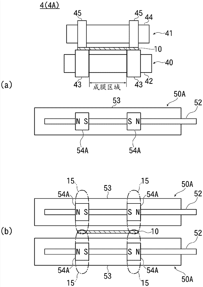
[0007] However, when the film is conveyed using such a traveling mechanism, there is a problem that the amount of charge due to static electricity becomes larger at both ends of the film sandwiched between the guide roller and the auxiliary roller than at the center.
[0008] Therefore, in the case of using such a traveling mechanism to transport and form a film, if the above-mentioned static elimination unit is used, the static elimination is performed by the plasma uniformly generated in the width direction of the film, so there is the following problem: The portion with a large amount of charge is fully eliminated. On the other hand, if the plasma caused by the discharge is to be strengthened to fully eliminate the portion with a large amount of charge, the film formation area on the film may be charged. Influenced by it, and the consumption and power consumption of the discharge electrode will increase, and if the static elimination unit is added, the structure of the device will be complicated and the size will be increased.

Method used


Image

  • Substrate destaticizing mechanism and vacuum treatment apparatus using same
  • Substrate destaticizing mechanism and vacuum treatment apparatus using same
  • Substrate destaticizing mechanism and vacuum treatment apparatus using same

Examples


Embodiment Construction

[0036] Hereinafter, embodiments of the present invention will be described with reference to the drawings.

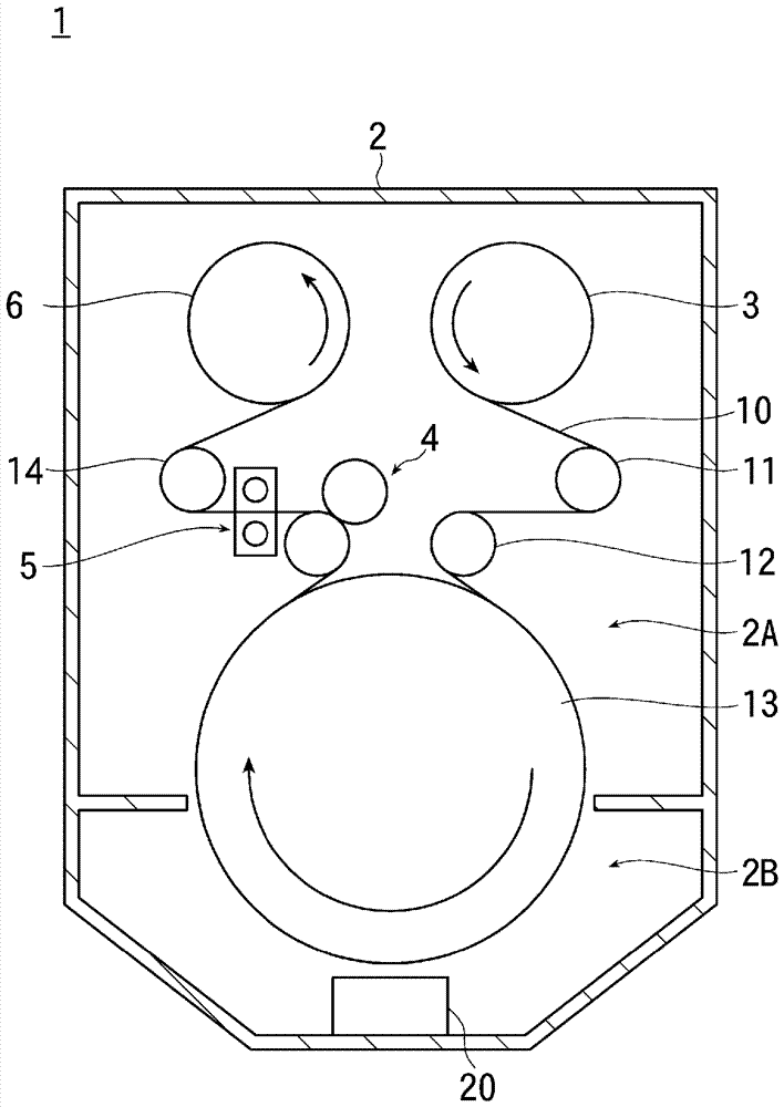
[0037] figure 1 It is a schematic configuration diagram showing an example of a roll-to-roll film forming apparatus as an embodiment of the present invention.

[0038] Below, take figure 1 The situation shown is taken as an example to illustrate the up-down relationship between components.

[0039] Such as figure 1 As shown, the roll-to-roll film forming apparatus (vacuum processing apparatus) 1 of the present embodiment includes a vacuum chamber 2 , has a feed / wind-up chamber 2A provided in the upper part of the vacuum chamber 2 , and a vacuum chamber 2A provided in the vacuum chamber 2 . The lower film forming chamber 2B.

[0040] The sending / winding chamber 2A and the film forming chamber 2B are respectively connected to an unillustrated vacuum exhaust system.

[0041] For example, in the upper part of the feeding / winding chamber 2A, there are provided a film-fo...


PUM


Abstract

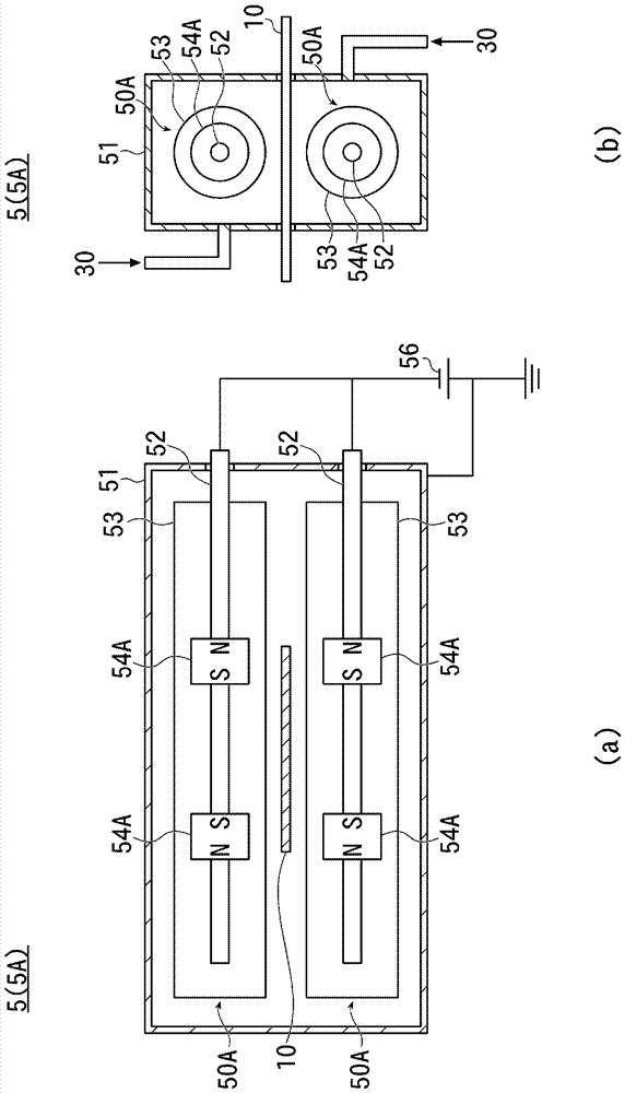
Provided is a technique which is used for, for example, devices for forming a film on a film-like substrate in vacuum and allows efficient destaticization using a simple structure without affecting atreated region. The present invention also provides a substrate destaticizing mechanism which destaticizes, by magnetron discharge, a film formation film 10 being transported in vacuum. According to the present invention, the substrate destaticizing mechanism comprises: a housing 51 to which a discharge gas is introduced; linear discharge electrodes 53 which are disposed perpendicular to the direction of transportation of the substrate in the housing 51 and to which a predetermined voltage is applied; and magnets 54A disposed near the discharge electrodes 53. The magnets 54A are disposed so asto cause an electrical discharge according to the distribution of the charge amount in the film formation film 10.

Description

technical field [0001] The present invention relates to the technology of removing electricity from a substrate in vacuum, and particularly relates to the technology of removing electricity from a film-shaped processing substrate. Background technique [0002] Conventionally, there has been known a take-up vacuum evaporation device that winds a long film-like substrate continuously sent out from a delivery roll onto a can roll for cooling, Evaporation substances from evaporation sources disposed opposite can rolls are vapor-deposited on a raw material film, and the vapor-deposited raw material film is wound up by a take-up roll (for example, refer to Patent Document 1). [0003] In such a take-up vacuum evaporation device, due to the influence of the charge remaining on the film, when the film is taken up on the take-up roll, wrinkles are generated on the film and the film cannot be taken up properly. . [0004] Therefore, in order to solve this problem, it has been propos...

Claims


Application Information

Patent Timeline
Patent Type & Authority Applications(China)
IPC IPC(8): C23C14/58C23C16/56
CPCC23C14/58C23C16/56C23C14/562C23C16/545
Inventor 广野贵启
Owner ULVAC INC
Learn More