
High-voltage power transmission line fault monitoring system

A high-voltage transmission line and fault monitoring technology, which is applied to fault locations, information technology support systems, and fault detection according to conductor types, can solve the problems of strict maintenance of helicopters, long time required for drones to hit high-voltage lines, etc., and achieve The effect of shortening the time to search for fault locations, speeding up troubleshooting and low monitoring costs

Inactive Publication Date: 2017-12-29
河北卫信电力科技有限公司 +1
View PDF5 Cites 2 Cited by
  • Summary
  • Abstract
  • Description
  • Claims
  • Application Information

AI Technical Summary

Problems solved by technology

This kind of monitoring method has the following defects: it needs to pay the mobile operator continuously; the signal cannot cover remote areas; due to the design factor is limited by the voltage level, it is only suitable for 10-35 kV distribution lines
This monitoring method has the following defects: helicopter inspection costs are high, and helicopter maintenance is strict; inspection attendance is greatly affected by the weather; helicopters fly at low altitudes on mountain routes and dense forest routes. Rich flying experience and skilled operation skills
This method has the following defects: the battery life of the UAV is limited; the distance between the UAV and the inspection line is difficult to control, and the complex geographical environment of the transmission line is likely to cause the UAV to collide with the high-voltage line; There is no standard for the collation of collected data and the research and judgment of defects
This monitoring method has the defects of labor-intensive, long-term and low-efficiency fault determination.

Method used


Image

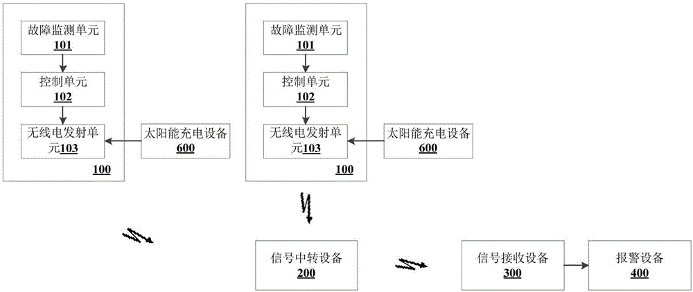
  • High-voltage power transmission line fault monitoring system
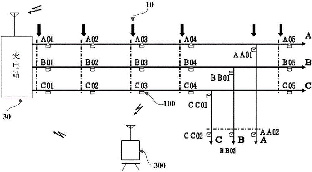
  • High-voltage power transmission line fault monitoring system
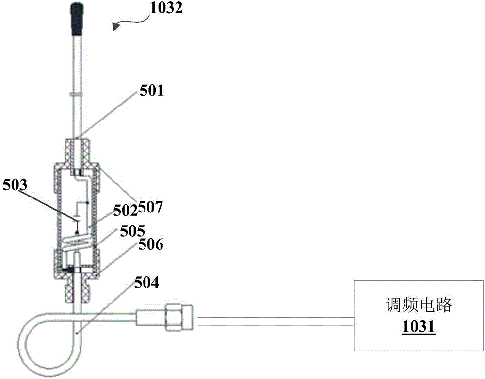
  • High-voltage power transmission line fault monitoring system

Examples


Embodiment Construction

[0036] In order to make the technical characteristics and effects of the present application more obvious, the technical solutions of the present application will be further described below in conjunction with the accompanying drawings. The present application can also be described or implemented with other different specific examples. The equivalent transformations made within all belong to the protection category of the present application.

[0037] In the description of this specification, descriptions referring to the terms "an embodiment", "a specific embodiment", "for example" and the like mean that the specific features, structures, materials or characteristics described in conjunction with the embodiment or example are included in this application. In at least one embodiment or example of . In this specification, schematic representations of the above terms do not necessarily refer to the same embodiment or example. Furthermore, the specific features, structures, mate...


PUM


Abstract

The application provides a high-voltage power transmission line fault monitoring system which comprises a plurality of monitoring devices, a signal relay device, a signal receiving device and an alarm device. Each monitoring device is arranged on a high-voltage power transmission line between power poles and comprises a fault monitoring unit, a control unit and a radio transmitting unit. The fault monitoring unit is used for monitoring the fault of the high-voltage power transmission line and sending the monitored fault information to the control unit. The control unit is used for receiving the fault information and sending the fault signal through the radio transmitting unit. The signal relay device is used for forwarding the fault signal. The signal receiving device is disposed in a transformer station, is connected with the alarm device, and is used for receiving and analyzing the fault signal to obtain the fault information and the identification information of the monitoring device, determining a fault location according to the identification information of the monitoring device, controlling the alarm device to prompt the fault information and the fault location. The high-voltage power transmission line fault monitoring system is not controlled by a communication operator, can reduce fault monitoring cost and shorten the time for searching for the fault location.

Description

technical field [0001] The application belongs to the field of high-voltage transmission line fault monitoring, in particular to a high-voltage transmission line fault monitoring system. Background technique [0002] Supply and distribution network overhead lines are one of the most prone to failure systems due to their long lines, many branches, complex network structure, and are easily affected by external forces and natural environments. Short-circuit faults and single-phase-to-earth faults are the most common types of faults. In the prior art, there are mainly four ways to determine a line fault as follows: [0003] 1. An addresser that uses GPRS and WCDMA signals of mobile telecom operators for data transmission. This monitoring method needs to install a mobile communication SIM card on the addresser. In order to save communication costs, a transfer station SIM card machine needs to be installed for every 6 addressers. This kind of monitoring method has the following...

Claims


Application Information

Patent Timeline
Patent Type & Authority Applications(China)
IPC IPC(8): G01R31/02G01R31/08
CPCG01R31/086G01R31/50Y04S10/52
Inventor 徐梓樵朱永利张彦兵
Owner 河北卫信电力科技有限公司
Learn More