
Air conditioner air deflector and air conditioner

A technology of air conditioner and air deflector, which is applied in space heating and ventilation details, heating methods, and prevention of condensed water. Improve the user experience, optimize the guiding effect, and eliminate the effect of negative pressure zone

Active Publication Date: 2017-12-29
QINGDAO HAIER AIR CONDITIONER GENERAL CORP LTD +1
View PDF5 Cites 6 Cited by
  • Summary
  • Abstract
  • Description
  • Claims
  • Application Information

AI Technical Summary

Problems solved by technology

However, the current air-conditioning air deflectors mainly have the following two problems: (1) When swinging the wind, the airflow blown out of the air duct directly impacts the air deflectors, the resistance of the air deflectors is large, the air volume loss of the whole machine is large, the noise of the air supply is increased, and the overall (2) When cooling, when there is a certain angle between the position of the air deflector and the direction of the air outlet, there will be condensation on the leeward side of the front end of the air deflector due to the backflow of humid air
With the improvement of users' demand for the appearance of the air conditioner's inner unit, more and more air conditioner air deflector structures are designed to be arc-shaped, and this arc-shaped structure will further worsen the condensation phenomenon of the air deflector

Method used


Image

  • Air conditioner air deflector and air conditioner
  • Air conditioner air deflector and air conditioner
  • Air conditioner air deflector and air conditioner

Examples


Embodiment Construction

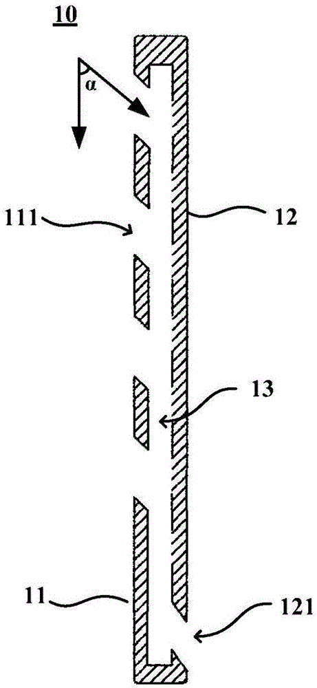
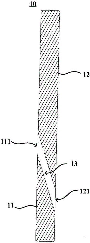
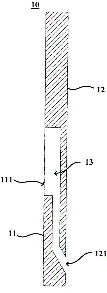
[0027] This embodiment provides an air deflector for an air conditioner, which can reduce or eliminate the negative pressure area of ​​the air deflector, guide the flow direction of the heat exchange airflow, reduce the friction between the heat exchange airflow and the air deflector, and prevent overheating The humid air is poured backwards to prevent condensation on the wind deflector and avoid affecting the user experience. figure 1 It is a side view of an air conditioner wind deflector 10 according to an embodiment of the present invention, as figure 1 As shown, the air deflector 10 of the air conditioner in this embodiment may generally include: a rear side panel 11 and a front side panel 12 .

[0028] Wherein, an air inlet 111 is opened in the middle and upper part of the rear side panel 11 for at least a part of the airflow blown out by the fan of the air conditioner to enter. The front side plate 12 is connected to the outside of the rear side plate 11, and an air flo...


PUM


Abstract

The invention provides an air conditioner air deflector and an air conditioner. The air conditioner air deflector comprises a rear side plate and a front side plate, wherein an air inlet is formed in the upper part of the rear side plate for allowing at least one part of air flow blown out by the fan of the air conditioner to enter; the front side plate is connected to the outer side of the rear side plate; an air flow channel 13 is formed between the front side plate and the rear side plate; and an air outlet is formed in the bottom of the front side plate for allowing air flow which enters the air flow channel 13 through the air inlet to guide out. According to the scheme adopted by the invention, the air flow channel 13 is formed between the rear side plate and the front side plate, and a combined structure of a double-layer plate and a middle hollow structure is adopted, so that at least one part of air flow enters the air flow channel 13 through the air inlet and is guided out from the air outlet, and therefore, a negative-pressure region of the air deflector can be reduced or eliminated; the flow direction of heat-exchange air flow can be guided, friction between the heat-exchange air flow and the air deflector is reduced, and warm and humid air can be prevented from flowing backwards, so that the air deflector is prevented from being condensed, and use experience of the user is prevented from being affected.

Description

technical field [0001] The invention relates to the technical field of air conditioning, in particular to an air deflector of an air conditioner and an air conditioner. Background technique [0002] With the development of society and the continuous improvement of people's living standards, environmental regulating appliances such as air conditioners are becoming more and more popular. As the performance and structural components of the air conditioner inner unit, the wind deflector is an indispensable part of the air conditioner. The wind deflector acts as a wind guide and has a certain static pressure recovery function. Its structural design has an important impact on the performance of the air conditioner and the user experience. However, the current air-conditioning air deflectors mainly have the following two problems: (1) When swinging the wind, the airflow blown out of the air duct directly impacts the air deflectors, the resistance of the air deflectors is large, th...

Claims


Application Information

Patent Timeline
IPC IPC(8): F24F13/08F24F13/22
CPCF24F13/081F24F13/22F24F2013/221
Inventor 王永涛王晓刚闫宝升
Owner QINGDAO HAIER AIR CONDITIONER GENERAL CORP LTD
Learn More