
Turbocharger bearing body structure with integral ball bearing

A technology of turbocharger and bearing body, applied in machine/engine, engine components, mechanical equipment, etc., can solve problems such as high reliability requirements and poor working conditions of ball bearings, and achieve reduced wear, simple structure, and sufficient lubrication. Effect

Pending Publication Date: 2017-12-29
HUNAN TYEN MACHINERY
View PDF0 Cites 4 Cited by
  • Summary
  • Abstract
  • Description
  • Claims
  • Application Information

AI Technical Summary

Problems solved by technology

[0002] In recent years, the application of turbochargers using ball bearings in small and medium-displacement automobile engines has attracted increasing attention at home and abroad due to their superior mechanical efficiency and transient response capabilities. However, due to the high speed of turbochargers, the general operating speed It can reach more than 100,000 revolutions per minute, and the highest can reach more than 200,000 revolutions per minute. The working conditions of ball bearings are harsh, and the requirements for reliability are relatively high.

Method used


Image

  • Turbocharger bearing body structure with integral ball bearing
  • Turbocharger bearing body structure with integral ball bearing
  • Turbocharger bearing body structure with integral ball bearing

Examples


Embodiment 1

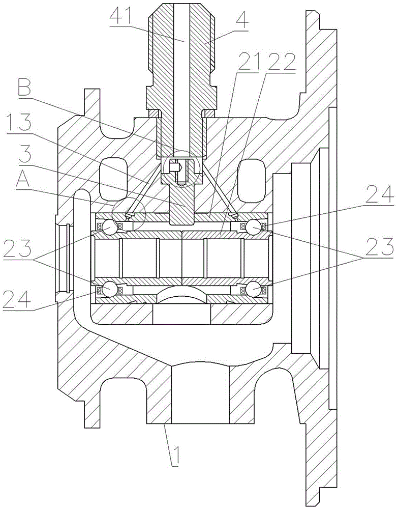
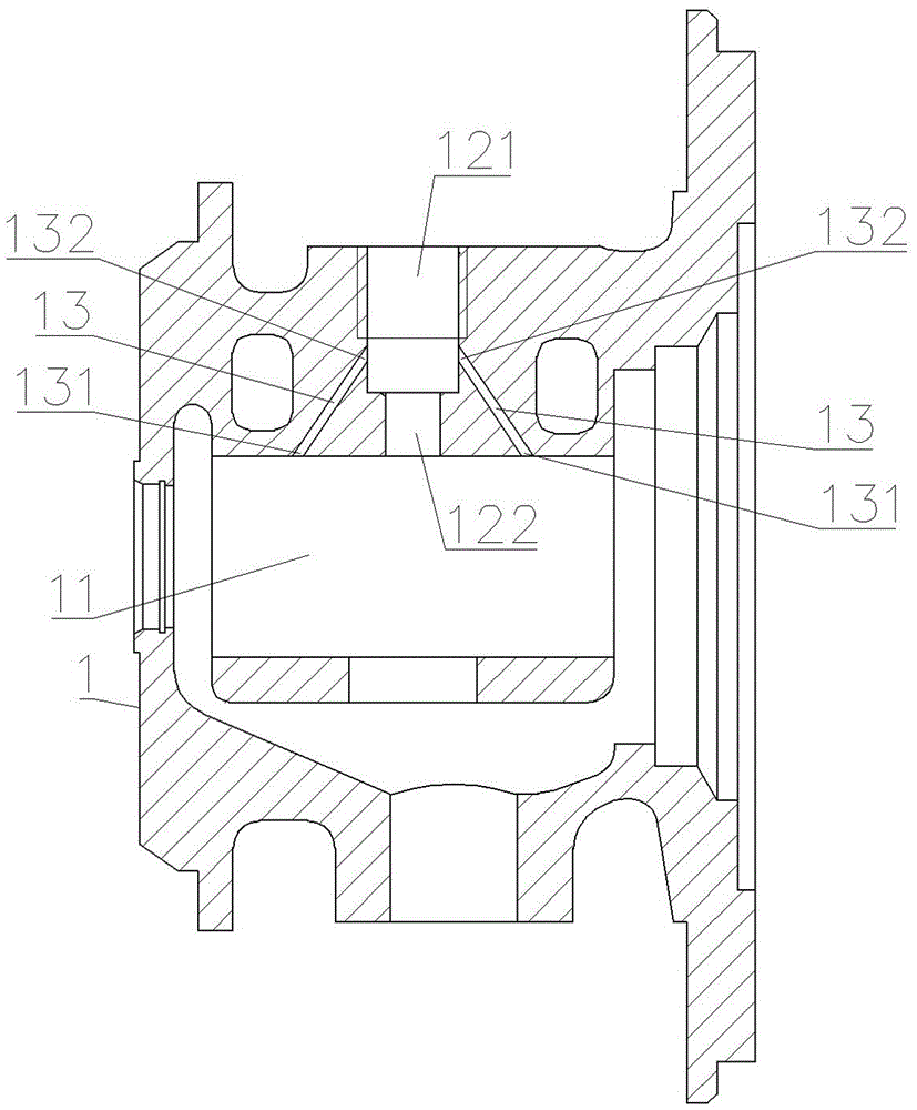
[0023] Such as Figure 1-4 As shown, the turbocharger bearing body structure with integral ball bearing includes bearing body 1, integral ball bearing, positioning pin 3 and oil inlet bolt 4.

[0024] The bearing body 1 is provided with an axial bearing hole 11, and the outer wall of the bearing body 1 is provided with a radial stepped hole. A section of the stepped hole close to the bearing hole 11 of the bearing body 1 is a pin hole A122;

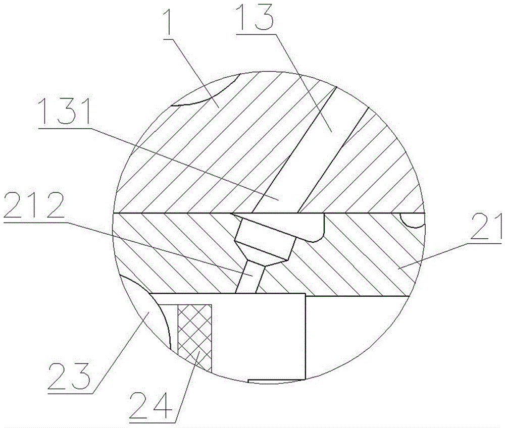
[0025] The integral ball bearing is installed in the bearing hole 11 of the bearing body 1 . The integral ball bearing includes an outer ring 21, an inner ring 22, a ceramic ball rolling body 23 and a cage 24. The outer ring 21 is provided with a pin hole B and a lubricating oil supply hole 212, and the lubricating oil supply hole 212 and the bearing body 1 enter oil. The oil outlet port 131 of the hole 13 is connected. There are two rows of ceramic ball rolling elements 23, and the two rows of ceramic ball rolling elements 23 are respe...


PUM


Abstract

The invention discloses a turbocharger bearing body structure with an integral ball bearing. The turbocharger bearing body structure comprises a bearing body, the integral ball bearing, a positioning pin and an oil inlet bolt; the integral ball bearing is arranged in a bearing hole of the bearing body; the upper end of the positioning pin is arranged in a pin hole A of the bearing body; the lower end of the positioning pin is inserted into a pin hole B of an outer ring of the integral ball bearing so as to fixedly connect the outer ring of the integral ball bearing with the bearing body; the lower end of the oil inlet bolt is connected to an inner threaded hole of the bearing body in a threaded mode; and the upper end of the oil inlet bolt is located outside the bearing body. Compared with the prior art which adopts the structure of two floating bearings, the turbocharger bearing body structure has the advantages that only one single integral ball bearing is adopted in the inner hole of the bearing body, and therefore the structure can be simpler, and the assembly can be more convenient; and an annular oil storage cavity is formed among the lower end surface of the oil inlet bolt, the outer wall of the positioning pin and the hole wall of a stepped hole, and therefore the problem that lubricating oil supply lags when an engine is started can be solved, and dry friction of the integral ball bearing in the initial rotation process can be avoided.

Description

technical field [0001] The invention relates to a bearing body structure of a turbocharger, in particular to a bearing body structure of a turbocharger with integral ball bearings. Background technique [0002] In recent years, the application of turbochargers using ball bearings in small and medium-displacement automobile engines has attracted increasing attention at home and abroad due to their superior mechanical efficiency and transient response capabilities. However, due to the high speed of turbochargers, the general operating speed It can reach hundreds of thousands of revolutions per minute, and the highest can reach more than two hundred thousand revolutions per minute. The working conditions of ball bearings are harsh, and the requirements for reliability are relatively high. Therefore, how to prolong the service life of the ball bearing and reduce the vibration and noise of the ball bearing under high-speed rotation is the focus of current research in the industry...

Claims


Application Information

Patent Timeline
Patent Type & Authority Applications(China)
IPC IPC(8): F01D25/16F01D25/18F02B39/14
CPCF01D25/16F01D25/18F02B39/14F05D2220/40Y02T10/12
Inventor 徐晓波程云荣刘石源杨国旗曾辉邓伟
Owner HUNAN TYEN MACHINERY
Learn More