


Quick Research
Generate reliable direction feasibility study reports for your R&D in just a few steps.

Technical Q&A
Discover and master advanced knowledge NOW. Basics, ideas, possibilities, all at once.

Find Solutions
As an expert in R&D theories, this can generate solutions to your technical problems instantly.

Evaluate Feasibility
Analyze your overall solution with one click, know your potential R&D risks in advance.

Monitor Landscape
Get weekly tech updates, stay abreast of the latest tech innovations and key insights.
Constant-tension paying-off device
A pay-off device, constant tension technology, applied in electrical components, inductance/transformer/magnet manufacturing, circuits, etc., can solve the problem of not ensuring the quality of windings, etc., and achieve the effect of perfect equipment, constant retracting force and good quality
- Summary
- Abstract
- Description
- Claims
- Application Information
AI Technical Summary
Problems solved by technology
Method used
Image

Examples
specific Embodiment approach 1
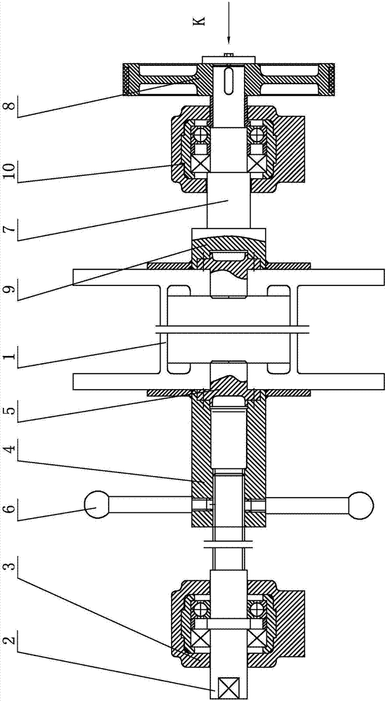
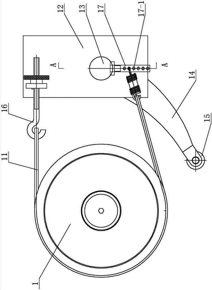
[0009] Specific implementation mode one: combine Figure 1 to Figure 3 This embodiment is described. A constant tension pay-off device in this embodiment includes a wire pulley 1, a pay-off drive assembly and a damping mechanism. The release drive assembly is installed on one side of the wire pulley 1, and the damping mechanism is installed The other side of wheel 1.
specific Embodiment approach 2
[0010] Specific implementation mode two: combination Figure 1 to Figure 3 Describe this embodiment, a constant tension pay-off device described in this embodiment, the pay-off drive assembly includes a drive shaft 2, a first bearing seat 3, a lock nut 4, a first small shaft 5 and a handle 6, the drive shaft 2 One end of the shaft is connected to the first bearing seat 3, the other end of the drive shaft 2 is connected to one side of the reel 1 through the small shaft 5, the lock nut 4 is set on the joint between the drive shaft 2 and the first small shaft 5, and the handle 6 Installed on the lock nut 4. Other components and connections are the same as those in the first embodiment.
specific Embodiment approach 3
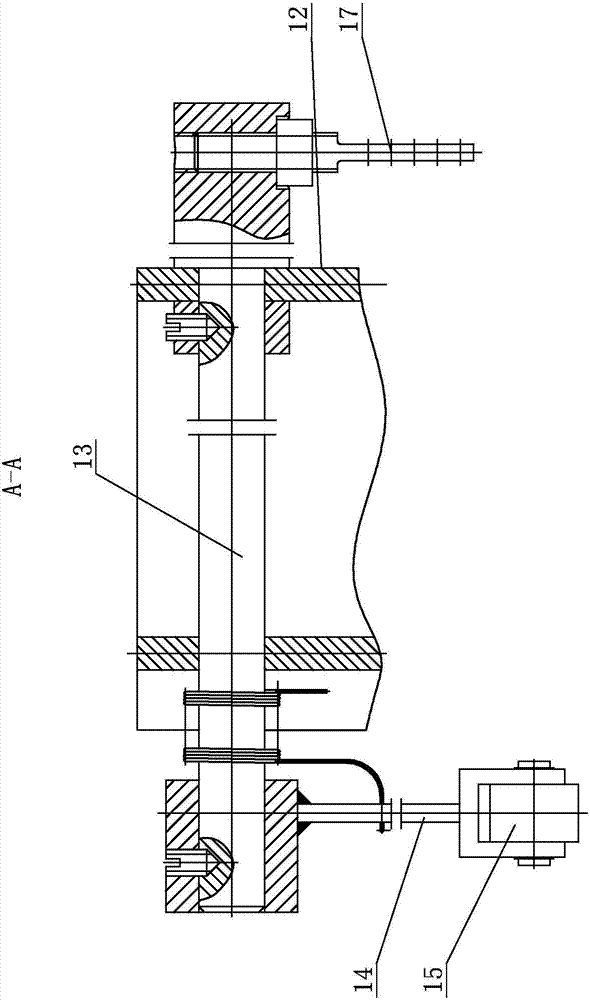
[0011] Specific implementation mode three: combination Figure 1 to Figure 3 Describe this embodiment, the damping mechanism of a constant tension pay-off device described in this embodiment includes a damping shaft 7, a damping wheel 8, a second small shaft 9, a second bearing seat 10, a brake pedestal 11 and a bracket assembly, and the damping shaft One end of 7 is connected to the other side of the wire wheel 1 through the second small shaft 9, the damping wheel 8 and the second bearing seat 10 are set on the other end of the damping shaft 7, and one end of the brake pedestal 11 is connected to the upper end of the bracket assembly , the other end of the brake pedestal 11 bypasses the damping wheel 8 and is connected to the lower end of the bracket assembly. Other components and connections are the same as those in the first embodiment.
PUM
 Abstract
Description
Claims
Application Information
 - R&D Engineer
- R&D Manager
- IP Professional
- Industry Leading Data Capabilities
- Powerful AI technology
- Patent DNA Extraction
Browse by: Latest US Patents, China's latest patents, Technical Efficacy Thesaurus, Application Domain, Technology Topic, Popular Technical Reports.
© 2024 PatSnap. All rights reserved.Legal|Privacy policy|Modern Slavery Act Transparency Statement|Sitemap|About US| Contact US: help@patsnap.com