Method and apparatus for determining the desired rotational speed of a bobbin drive roll

A technology for driving rollers and bobbins, which is used in transportation and packaging, thin material handling, and transportation of filamentous materials, etc., and can solve problems such as negative effects of subsequent processes and quality problems.

Active Publication Date: 2017-09-01
SAURER GERMANY GMBH & CO KG
View PDF4 Cites 0 Cited by
  • Summary
  • Abstract
  • Description
  • Claims
  • Application Information

AI Technical Summary

Problems solved by technology

But this has quality issues and negatively affects subsequent processes

Method used


Image

  • Method and apparatus for determining the desired rotational speed of a bobbin drive roll
  • Method and apparatus for determining the desired rotational speed of a bobbin drive roll

Examples


Embodiment Construction

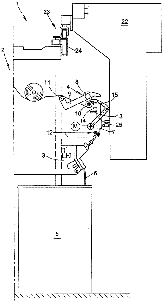
[0019] figure 1 A side view of the station 2 of the open-end rotor spinning machine 1 is shown. Such an open-end rotor spinning machine 1 has a plurality of such workstations 2 arranged side by side in each case on its two machine longitudinal sides. Here, the structure and working principle of the stations 2 are the same, so only one station 2 will be used for description.

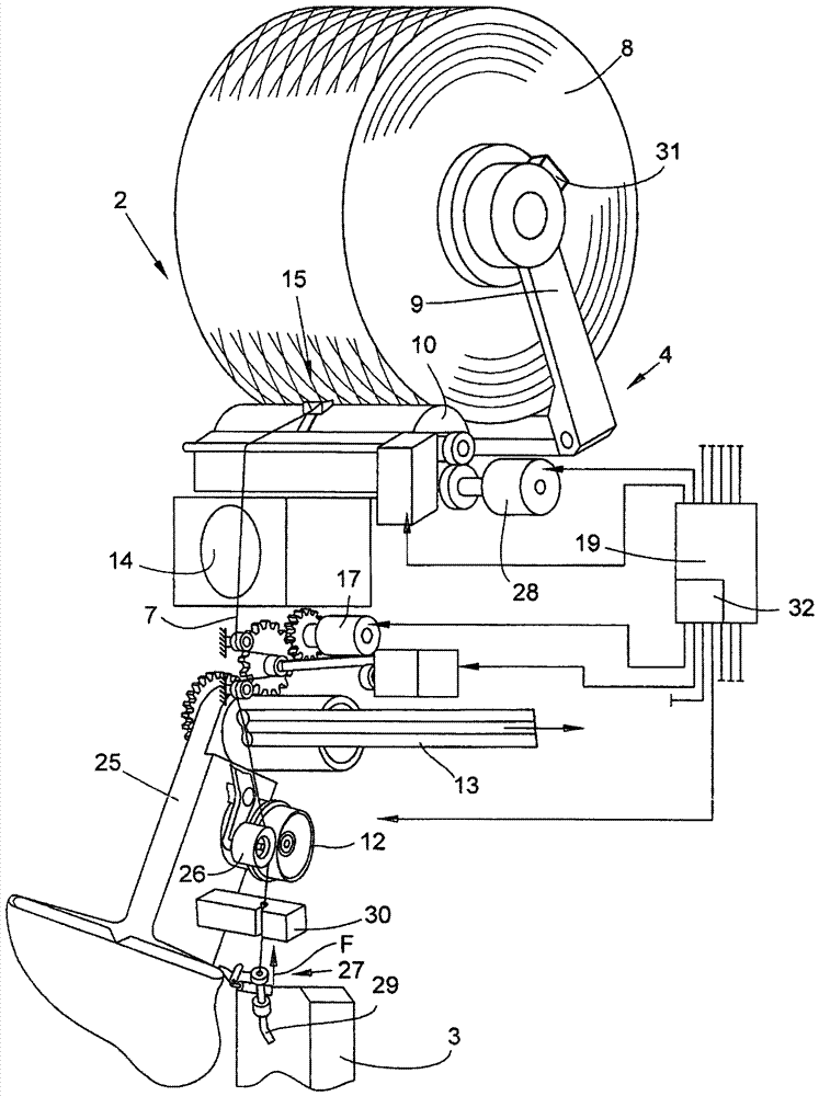
[0020] figure 1 with figure 2 Shown is a station 2 with an open-end spinning device 3 and a winding device 4 including a suction nozzle 25 . As is known, a fiber sliver 6 stored in a spinning barrel 5 is spun into a yarn 7 in an open-end spinning device 3 . The yarn 7 is then wound onto a cross-wound bobbin 8 in the winding device 4 . The cross-wound bobbin 8 is held in the winding device 4 on the creel 9 during the spinning / winding process, where it is driven by a bobbin drive roller 10 with a friction fit. The creel 9 is pivotably mounted about a pivot axis 11 .

[0021] The yarn 7 is drawn out ...


PUM


Abstract

The method involves supplying the thread by a yarn outlet unit in a continuous manner, where the sensory rotation pulses of a cross-wound bobbin (8) are detected. The timing of the rotation pulses is measured such that the respective driving diameter of the conical cross-wound bobbin is calculated. The speed of the bobbin drive roller (10) is balanced on the driving diameter. The detection of the speed pulses takes place before an application process at a non-wound cross-wound bobbin. An independent claim is included for a working station with a control unit.

Description

technical field [0001] The invention relates to a method for determining the required rotational speed of a bobbin drive roller when driving a tapered sleeve or a cross-wound bobbin held at a station of a textile machine for producing cross-wound bobbins In a creel in which independently motor-controlled bobbin drive rollers of stations frictionally drive the tapered sleeve and the subsequent cross-wound bobbins; the invention also relates to a textile machine for the manufacture of cross-wound bobbins carrying out said method. Background technique [0002] In the workstations of spinning machines, in so-called winding machines, not only cylindrical but also conical bobbins are produced, it is especially important to feed the yarn with a constant winding tension with regard to its uniform bobbin structure. Yarn winding tension not only has a decisive influence on the structural quality of the package, but also affects the continuous progress of the spinning or winding proces...

Claims


Application Information

Patent Timeline
Patent Type & Authority Patents(China)
IPC IPC(8): B65H54/42
CPCB65H51/205B65H54/103B65H54/42B65H2701/31
Inventor 海因茨-迪特尔·戈培尔海因茨-约瑟夫·波伊克京特·舍尔
Owner SAURER GERMANY GMBH & CO KG
Why Eureka
Try Eureka