Cable for easy mounting and positioning

An installation and positioning, optical cable technology, applied in optical fiber/cable installation, optics, light guide and other directions, can solve problems such as breakage, signal influence, easy to be blown off, etc., to achieve a broad application market, avoid accidents, and facilitate installation and positioning. Effect

Pending Publication Date: 2017-12-26
SUZHOU SHENGXIN OPTOELECTRONICS TECH
View PDF1 Cites 3 Cited by
  • Summary
  • Abstract
  • Description
  • Claims
  • Application Information

AI Technical Summary

Problems solved by technology

[0004] However, the structure of this invention is not ideal enough, and the installation and positioning of the optical cable erected at high altitude is not firm enough. When encountering strong winds, it is easy to loosen and be blown off, causing greater losses. Moreover, the composite optical cable does not have a transmission loop, shielding Poor performance, the signal is easily affected, and there will be gaps in the filling rope between the cable cores, the sealing effect is not good enough, moisture is easy to invade the inside of the cable, reducing the insulation and waterproof effect, and the softness of the composite cable is not enough Well, in some special occasions, it is easy to be damaged and broken, which will cause the cable core of the optical cable to break, resulting in increased attenuation and shortened service life, which is far from meeting the current people's requirements for this product.

Method used


Image

  • Cable for easy mounting and positioning
  • Cable for easy mounting and positioning
  • Cable for easy mounting and positioning

Examples


Embodiment Construction

[0020] The following will clearly and completely describe the technical solutions in the embodiments of the present invention with reference to the accompanying drawings in the embodiments of the present invention. Obviously, the described embodiments are only some, not all, embodiments of the present invention. Based on the embodiments of the present invention, all other embodiments obtained by persons of ordinary skill in the art without making creative efforts belong to the protection scope of the present invention.

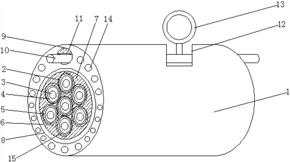
[0021] see Figure 1-Figure 3 , the present invention provides a technical solution: an optical cable for easy installation and positioning, including an outer sheath 1, the inner cavity of the outer sheath 1 is provided with a plurality of optical cable cores 2, and the optical cable cores 2 are sequentially provided with The optical fiber 3, the insulating layer 4 and the aluminum foil layer 5, and the optical fiber 3, the insulating layer 4 and the aluminum...


PUM


Abstract

The invention discloses a cable for easy mounting and positioning, which comprises an outer sheath; the inner cavity of the outer sheath is provided with several cable cores, and the cable cores are orderly provided with a light guide fiber, an insulation layer and an aluminum foil layer from inside to outside; the light guide fiber, the insulation layer and the aluminum foil layer are sleeved and connected to each other; a weaving layer sleeves at the outside of the cable core, and the outside of the weaving layer is provided with a binding layer; a filler is filled between the binding layer and the cable core, and coats at the outside of the weaving layer; the outside of the binding layer sleeves with a flame retarding layer, and the outside of the flame retarding layer bonds to the inner wall of the outer sheath; the upper part of the flame retarding layer is provided with a channel, and a reinforcing rib is arranged in the channel. The cable for easy mounting and positioning is simple and stable in structure, tensile and durable, and convenient to mount and position, and able to prevent moisture and retard inflaming; the anti-bending performance is good, and the using scale is enlarged; therefore, the cable for easy mounting and positioning has wide application prospect.

Description

technical field [0001] The invention relates to the field of optical communication transmission equipment, in particular to an optical cable which is convenient for installation and positioning. Background technique [0002] Optical cables are manufactured to meet optical, mechanical or environmental performance specifications. It is a communication cable assembly that uses one or more optical fibers placed in a sheath as a transmission medium and can be used individually or in groups. Optical cables It is mainly composed of optical fiber, plastic protective sleeve and plastic sheath. There is no metal such as gold, silver, copper and aluminum in the optical cable, and generally has no recycling value. The optical cable is a cable core composed of a certain number of optical fibers in a certain way, and the outer sheath is covered. Some are also coated with an outer sheath, which is used to realize a communication line for optical signal transmission. It is very important fo...

Claims


Application Information

Patent Timeline
IPC IPC(8): G02B6/44G02B6/46
CPCG02B6/46G02B6/443G02B6/4432G02B6/4436G02B6/44384
Inventor 王伟平俞兴明李寰
Owner SUZHOU SHENGXIN OPTOELECTRONICS TECH
Why Eureka
Try Eureka