Automatic through hole cleaning equipment for spinneret components

A technology for spinneret components and cleaning equipment, which is applied to spinneret assemblies, textiles, and papermaking. It can solve the problems of complicated cleaning process, high cleaning cost, and scrapped spinnerets, so as to achieve good cleaning effect and improve through-hole Work efficiency, improve continuous new effect

Pending Publication Date: 2017-12-26
李荣春
View PDF19 Cites 10 Cited by
  • Summary
  • Abstract
  • Description
  • Claims
  • Application Information

AI Technical Summary

Problems solved by technology

[0013] The purpose of the present invention is to solve the problem of low cleaning efficiency and high pollution in the existing calcination spinneret technology, or the technical problem that the cleaning process is complicated and easily deforms the spinneret, which directly leads to the scrapping of the spinneret. An automatic through-hole cleaning device for a spinneret assembly. The invention flushes the spinneret assembly with high-pressure water and realizes the precise and controllable displacement and positioning of the spinneret holes by the high-pressure water body through a displacement control mechanism. The surface of the spinneret assembly and each extremely small spinneret hole are cleaned efficiently and completely, which has the advantages of high precision, high efficiency and good cleaning effect. The whole cleaning process is simple, easy to operate, has the effect of environmental protection and energy saving, and realizes automation. At the same time, the high-pressure gas system can dry the spinneret assembly, realizing the technical effect of washing and using immediately, and solving the problems of high time consumption, low cleaning efficiency, high cleaning cost and existing environmental problems in the existing cleaning technology. pollution problem

Method used


Image

  • Automatic through hole cleaning equipment for spinneret components
  • Automatic through hole cleaning equipment for spinneret components
  • Automatic through hole cleaning equipment for spinneret components

Examples


Embodiment 1

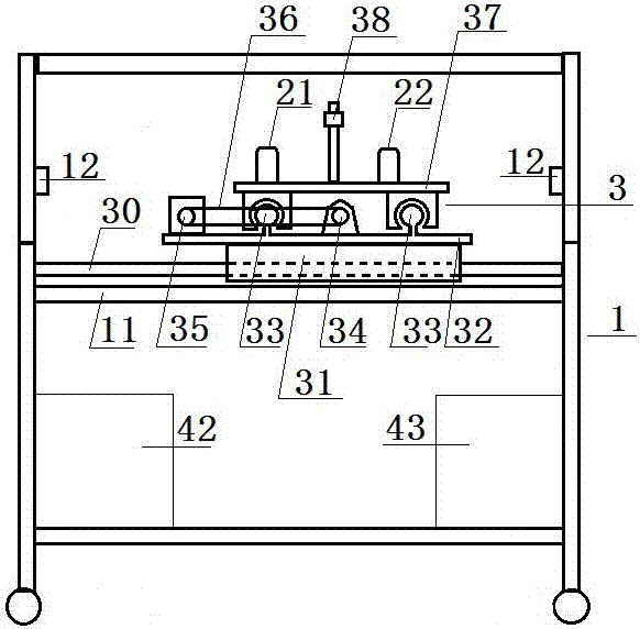
[0065] as attached figure 2 As shown, the automatic through-hole cleaning equipment for the spinneret assembly described in this embodiment includes a support 1, and a cleaning area 13 and a displacement control of adjacent cleaning areas are arranged on the support along the width direction of the support. District 14.

[0066] A high-pressure water body cleaning system is provided on the support 1, and a stage 12 for carrying the spinneret assembly is arranged in the cleaning area 13; the high-pressure water body cleaning system is above the spinneret assembly or / and A high-pressure water jet is generated below to remove attachments attached to the surface layer of the spinneret assembly or / and in the spinneret holes.

[0067] The high-pressure water jet produced by the high-pressure water cleaning system of this embodiment efficiently removes attachments attached to the surface layer of the spinneret assembly or / and inside the spinneret hole by adjusting the water pressur...

Embodiment 2

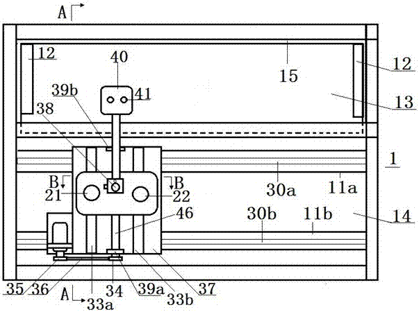
[0069] In this embodiment, on the basis of the high-pressure water body cleaning system in Embodiment 1, a displacement control mechanism and a control system are further provided. as attached figure 1 , figure 2 As shown, the displacement control mechanism 3 is arranged in the displacement control area 14 and is connected with the high-pressure water body cleaning system for driving the high-pressure water body jet along the transverse direction or / and longitudinal direction of the spinneret assembly For reciprocating motion. as attached Figure 5 As shown, the control system is composed of a touch screen 101 and a PLC 100 connected to the touch screen, and the PLC 100 is respectively connected to the displacement control mechanism 3 and the high-pressure water body cleaning system.

[0070] The displacement control mechanism and control system implemented in this implementation realize the automatic cleaning effect of the high-pressure water body cleaning system, which n...

Embodiment 3

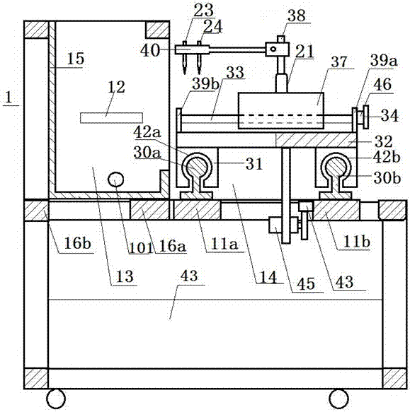
[0072] This embodiment provides a further specific implementation manner for the displacement control mechanism of the second embodiment. as attached Figure 1 to Figure 3 As shown, the displacement control mechanism 3 includes: a longitudinal motion control mechanism 32, a lateral motion control mechanism 37 and a cleaning support platform, wherein: the longitudinal movement control mechanism 32 is used to drive the cleaning support platform to move along the longitudinal direction of the spinneret assembly. For reciprocating motion, a lateral motion control mechanism 37 is provided above the longitudinal motion control mechanism 32 for driving the cleaning support platform to reciprocate along the lateral direction of the spinneret assembly. The cleaning support platform is set above the lateral motion control mechanism 37, the cleaning support platform includes a leg end 38, a support platform end 40, and the leg end 38 is vertically fixedly connected to the end face of the...


PUM

PropertyMeasurementUnit
diameteraaaaaaaaaa

Abstract

The invention relates to automatic through hole cleaning equipment for spinneret components. The automatic through hole cleaning equipment comprises a support provided with a cleaning area and a displacement control area, and the cleaning area is provided with a high-pressure water cleaning system and an object bearing table which is used for bearing the spinneret components; the high-pressure water cleaning system generates high-pressure water jet flow above or/and below the spinneret components, and the jet flow is used for cleaning attachments on the surface layers of the spinneret components or/and in the spinneret holes; the displacement control area is internally provided with a displacement control mechanism and a control system, and the displacement control mechanism is used for driving the high-pressure water jet flow to conduct reciprocating displacement motion in the horizontal direction or the longitudinal direction of the spinneret components. The control system comprises a touch display screen and a PLC, and the PLC is connected with the displacement control mechanism and the high-pressure water cleaning system separately. Besides, a high-pressure gas system which is used for generating high-pressure gas flow and is connected with the PLC and the displacement control mechanism separately can be further arranged, and is used for cleaning the attachments attached to the surface layers of the spinneret components or/and in the spinneret holes.

Description

technical field [0001] The invention relates to the field of equipment, in particular to an automatic through-hole cleaning equipment for a spinning assembly and its application in the field of fiber preparation. Background technique [0002] For fiber quality, the quality of spinning equipment is very important. As a filament-forming element in chemical fiber spinning, the spinneret has a wide range of application values ​​in chemical fiber spinning. Since the spinneret is a cycle that needs to be used repeatedly Spinning parts, so when the spinneret is used for a period of time or replaced with other spinnerets, it is necessary to clean the replaced spinneret for the next use. [0003] However, the spinneret is an alloy plate with a diameter of 5cm to 20cm and a thickness of only a few mm. There are one thousand to hundreds of thousands of spinneret holes evenly arranged on it according to a certain distribution. The diameter of the spinneret holes is as small as four. Fi...

Claims


Application Information

Patent Timeline
Patent Type & Authority Applications(China)
IPC IPC(8): D01D4/04
CPCD01D4/04
Inventor 李荣春
Owner 李荣春
Why Eureka
Try Eureka