
Vacuum tube gate-control modulator implementing method based on optical fiber couplers

A technology of fiber optic coupler and implementation method, which is applied in pulse shaping and other directions, and can solve problems such as poor maintainability, complex high-voltage circuits, and susceptibility to interference

Inactive Publication Date: 2017-12-22
THE 724TH RES INST OF CHINA SHIPBUILDING IND
View PDF8 Cites 2 Cited by
  • Summary
  • Abstract
  • Description
  • Claims
  • Application Information

AI Technical Summary

Problems solved by technology

[0004] The current gate-controlled modulators use a pulse transformer to isolate the "start trigger pulse" and "truncated trigger pulse" and transmit them to the high-voltage circuit. After high-voltage amplification and shaping, a high-potential high-voltage modulated pulse is formed. The pulse transformer in this method is bulky, the high-voltage circuit is complex and susceptible to interference, and the maintainability is poor. The forming circuit is placed on the low-voltage side, and only the pulse amplification and shaping functions are realized in the high-voltage, which not only effectively improves the reliability but also reduces the weight and volume of the modulator

Method used


Image

  • Vacuum tube gate-control modulator implementing method based on optical fiber couplers
  • Vacuum tube gate-control modulator implementing method based on optical fiber couplers

Examples


Embodiment Construction

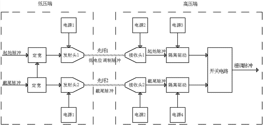
[0012] Realization principle of the present invention sees figure 2 , the implementation method is:

[0013] 1. Formation of modulated pulse and truncated pulse

[0014] The modulation pulse is formed by monostable or flip-flop circuits, the initial trigger pulse generates the modulation pulse, and the truncated trigger pulse turns off the modulated pulse; the truncated trigger pulse simultaneously generates a truncated pulse with a width of 5 to 30 μS

[0015] 2. Realization method of high-voltage isolated transmission circuit of modulated pulse

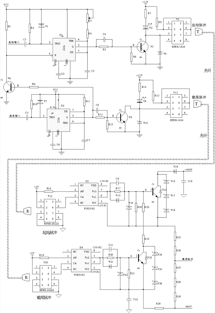
[0016] Two sets of optical fiber components and their driving circuits are selected. Optical fiber component devices are composed of electro-optic conversion devices, optical fibers, and electro-optic conversion devices.

[0017] The drive circuit can be realized by using a switch tube, and the modulated pulse signal or truncated pulse formed in the previous step is sent to the control electrode of the electro-optic device for a...


PUM


Abstract

The invention relates to a vacuum tube gate-control modulator implementing method based on optical fiber couplers. In a vacuum tube transmitter, a gate-control modulator usually needs to be used for carrying out modulation on a gate electrode of a vacuum tube so as to control working of the vacuum tube, and the gate-control modulator simultaneously has the difficult problems of high-voltage isolation, high-voltage amplification and waveform quality. According to the invention, firstly, a low-potential modulating pulse and a chopped pulse are formed at a low-voltage circuit, and two groups of optical fiber couplers and a certain length of optical fiber are adopted to implement high-voltage isolation transmission of the modulating pulse and the chopped pulse; and secondly, two groups of optical isolation MOSFET driving chips and MOS tubes are adopted to carry out amplification and shaping on the modulating pulse to form a high-potential high-voltage modulating pulse. A principle of the method disclosed by the invention is as shown in the accompanying drawings. According to the invention, due to a case of adopting the optical fiber to carry out high-voltage isolation, the vacuum tube gate-control modulator implementing method has the advantages of high withstand voltage and resistance to striking impact; a photoelectric device is easy to implement the wide-pulse high-duty-ratio modulator; and output adopts a double-switching-tube opposite-pulling shaping circuit so as to well solve the problem of waveform of the modulating pulse.

Description

technical field [0001] The invention belongs to the technique of grid control modulator for radar transmitter. Background technique [0002] Grid modulation is a commonly used modulation method for vacuum tube transmitters. Its basic working method is to control the pulse power output of the TWT by controlling the turn-on timing of the initial and truncated switch tubes, so that the positive bias power supply and the negative bias power supply are applied to the grid of the TWT in turn. [0003] In vacuum tube transmitters, it is often necessary to use a grid-controlled modulator to modulate the grid of the vacuum tube to control the work of the vacuum tube. The grid-controlled modulator generally works at the high potential of the cathode (usually tens of thousands of volts), and the output pulse amplitude is about It is about 800V. In order to control the launch or shut down of the transmitting device in an orderly manner, the whole device controls the launch of the trans...

Claims


Application Information

Patent Timeline
Patent Type & Authority Applications(China)
IPC IPC(8): H03K5/02
CPCH03K5/02
Inventor 蔡宝龙李东辉
Owner THE 724TH RES INST OF CHINA SHIPBUILDING IND
Learn More