
Drag reduced conductor and method for forming spline curves in drag reduced conductor

A spline curve, wire technology, applied in the direction of power cables, conductors, etc. used to form ripples on conductors/cables, with shielding layers/conducting layers, can solve the problem of reducing wind pressure coefficient, high production cost, inconspicuous, etc. problems, to achieve the effect of reducing the resistance coefficient, facilitating processing and production, and reducing wind pressure

Pending Publication Date: 2017-12-22
NANJING UNIV OF AERONAUTICS & ASTRONAUTICS +2
View PDF0 Cites 2 Cited by
  • Summary
  • Abstract
  • Description
  • Claims
  • Application Information

AI Technical Summary

Problems solved by technology

The outermost layer of the stranded wire is three structural types of molded wires. When producing a single wire, it is necessary to design the drawing dies corresponding to the three types of wires, and the production cost is relatively high.
[0010] 2. The production of wires is complicated
[0011] 3. The r-depth of the V-shaped groove structure is not easy to determine, and the deep groove and the fan-shaped surface cannot smoothly transition, resulting in an insignificant reduction in the wind pressure coefficient

Method used


Image

  • Drag reduced conductor and method for forming spline curves in drag reduced conductor
  • Drag reduced conductor and method for forming spline curves in drag reduced conductor
  • Drag reduced conductor and method for forming spline curves in drag reduced conductor

Examples


Embodiment Construction

[0031] Below in conjunction with accompanying drawing and specific embodiment, further illustrate the present invention, should be understood that these embodiments are only for illustrating the present invention and are not intended to limit the scope of the present invention, after having read the present invention, those skilled in the art will understand various aspects of the present invention Modifications in equivalent forms all fall within the scope defined by the appended claims of this application.

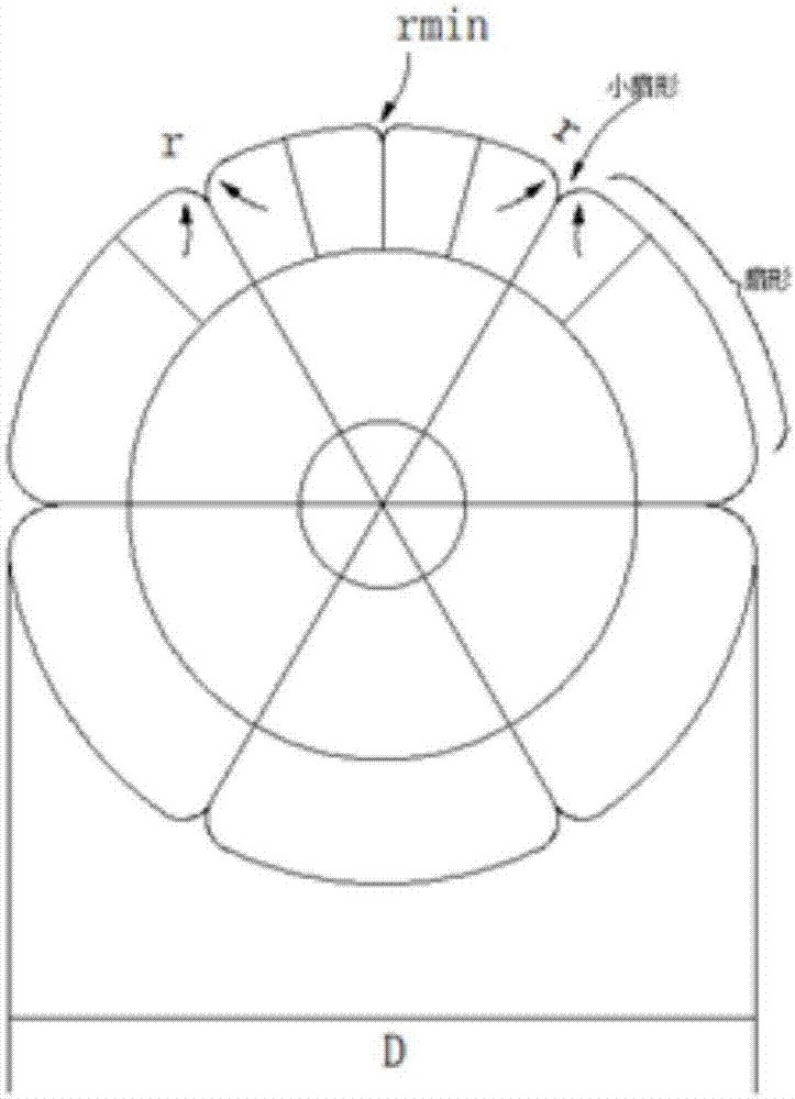
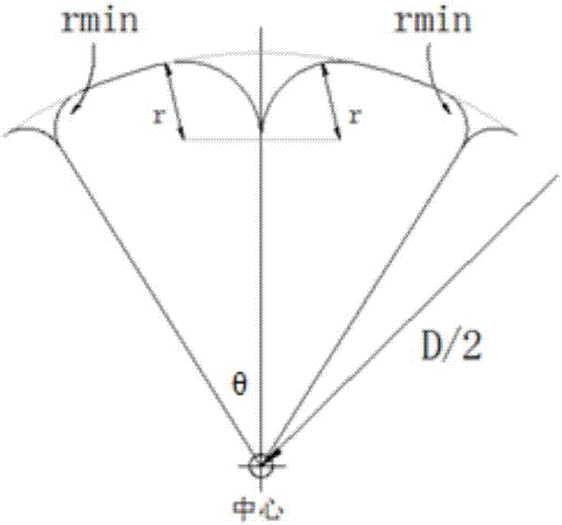
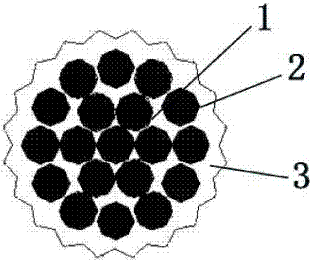
[0032] Such as Figure 3 to Figure 5 As shown, a low wind pressure wire includes an inner conductor layer 1 composed of aluminum wires, an outer conductor layer 2 composed of aluminum wires wrapped around the inner conductor layer, and an aluminum wire layer 3 arranged outside the outer conductor layer. The surface structure of the aluminum wire layer 3 is a spline curve with the same local structure form in multiple sections, and the shape of each section of the spline ...


PUM


Abstract

The invention discloses a drag reduced conductor and a method for forming spline curves in the drag reduced conductor. The drag reduced conductor includes an inner conductor layer composed of aluminum wires, an outer conductor layer which wraps the periphery of the inner conductor layer and is composed of aluminum wires, and an aluminum wire layer arranged outside the outer conductor layer; the surface structure of the aluminum wire layer is composed of a plurality of spline curves with the same local structure; and the shape of each spline curve is defined by two control points at the highest points at two ends of the corresponding spline curve and a distance from a point on the angular bisector of the two control points to the outer diameter of the conductor. According to the drag reduced conductor and the method for forming the spline curves in the drag reduced conductor of the invention, the aluminum wire structures of the outermost layer of the conductor are changed in a manner that traditional circular lines and fan-shaped structures are changed into curved line structures, and therefore, the surface of the conductor has a certain roughness, and therefore, drag can be reduced. The structures of the molded lines are monotonous, and therefore, molds for producing the molded lines can be monotonous, the lines will not be disordered when being stranded, and processing and production can be facilitated.

Description

Technical field: [0001] The invention relates to the technical field of electric power transmission, in particular to a low wind pressure wire and a method for forming a spline curve in the low wind pressure wire. Background technique: [0002] The wind pressure on the wires in the overhead transmission line accounts for about 50% to 70% of the wind pressure on the entire transmission line. In addition to its own strength to resist the effect of wind load, the support tower of the wire must also bear the combined effect of the wind load transmitted by the wire and the wind load received by the tower itself. [0003] The wind pressure of the conductor has a significant impact on the strength design of the tower foundation and the tower body. Reducing the wind pressure of the conductor is of great significance for reducing the cost of the line and improving the safety of the line operation. [0004] For a long time, line workers in relevant countries have always paid attentio...

Claims


Application Information

Patent Timeline
IPC IPC(8): H01B5/08H01B9/00H01B13/00H01B9/02
CPCH01B5/08H01B9/006H01B9/008H01B9/02H01B13/0009
Inventor 张军吴恙吴明埝缪姚军
Owner NANJING UNIV OF AERONAUTICS & ASTRONAUTICS
Learn More