Face frame and display
A face frame and outer frame technology, which is applied in the field of the face frame and the display to which the face frame is applied, can solve problems such as inability to transform or change
- Summary
- Abstract
- Description
- Claims
- Application Information
AI Technical Summary
Problems solved by technology
Method used
Image
Examples
Embodiment 1
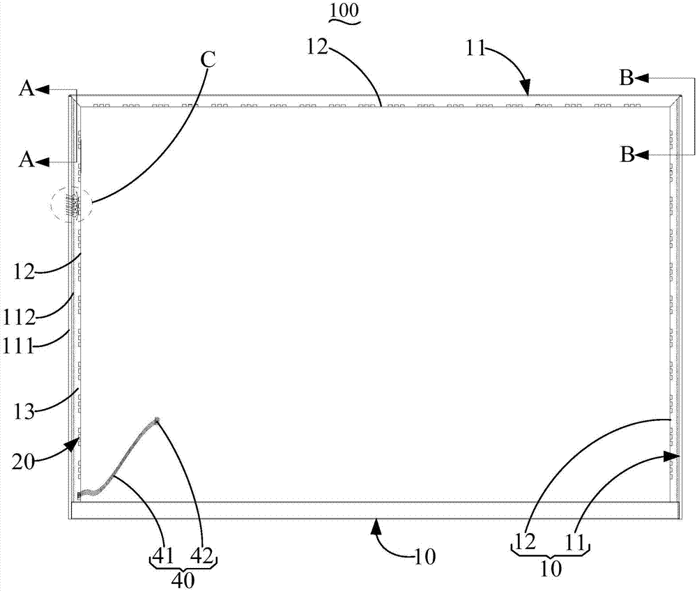
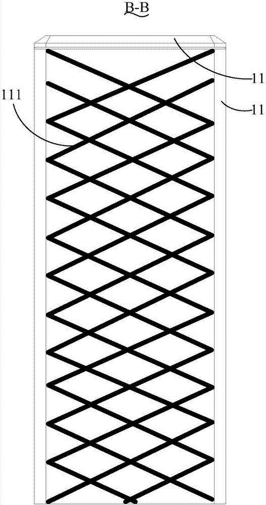
[0032] see Figure 1 to Figure 4 , in an embodiment of the present invention, the surface frame 100 includes a frame body 10 and at least three lamp groups 20 of different colors, the lamp groups 20 are arranged at intervals, the frame body 10 includes an outer frame 11 and an inner frame 12 accommodated in the outer frame 11 The outer frame 11 and the inner frame 12 form an accommodation space 13, and the lamp group 20 is accommodated in the accommodation space 13. The inner wall of the outer frame 11 is provided with a plurality of grooves 112 communicating with the accommodation space 13, and the plurality of grooves 112 are arranged in a grid. Cloth, the lamp group 20 faces the groove 112 .
[0033] The outer frame 11 can be a transparent acrylic material, the outer frame 11 includes four interconnected outer frames, each outer frame is formed with a cavity, and the inner frame 12 includes four interconnected inner frames, one inner frame is accommodated and connected to a...
Embodiment 2
[0041] See 5 to Figure 6 , the face frame 100 of this embodiment also includes a partition 14 accommodated in the accommodation space 13, and at least one light guide 30. The partition 14 separates the accommodation space 13 to divide the accommodation space 13 into a first space and a second space. Space, the lamp set 20 is disposed on the light guide 30, and the lamp set 20 and the light guide 30 are accommodated in the first space.
[0042] The separator 14 can be made of plastic or lightweight alloy material, and it can be produced by integral injection molding. In this embodiment, the lamp group 20 abuts against one end surface of the light guide 30, effectively maximizing the light of the lamp group 20 Inject into the light guide 30 to avoid energy loss.
[0043] In this embodiment, the two ends of the light guide 30 respectively extend to the two ends of the first space, and the three-color light is mixed and transmitted in the light guide 30 to form corresponding col...
Embodiment 3
[0047] See 7 to Figure 8 , the surface frame 100 of this embodiment is provided with several light guides 30, and each lamp group 20 includes at least one lamp bead 21 and a condenser lens 22 sleeved on the lamp bead 21, a light guide 30 and a condenser lens 22 connections.
[0048] When the lamp bead 21 is turned on, the light is focused by the condenser lens 22 and injected into the bottom of the light guide 30, which effectively improves the transmission efficiency and reduces the loss of light energy. One lamp group 20 emits light of one color to a single light guide 30 to further improve the transmission efficiency; Refraction and reflection will form multiple mixes to effectively form colored light and realize the color changing function.
[0049] Preferably, the light guide of this embodiment includes a cladding 32 , a fiber core 31 accommodated in the cladding 32 , and a coating layer 33 provided on the surface of the cladding 32 .
[0050] The coating layer 33 is ...
PUM
 Abstract
Description
Claims
Application Information
 - Generate Ideas
- Intellectual Property
- Life Sciences
- Materials
- Tech Scout
- Unparalleled Data Quality
- Higher Quality Content
- 60% Fewer Hallucinations
Browse by: Latest US Patents, China's latest patents, Technical Efficacy Thesaurus, Application Domain, Technology Topic, Popular Technical Reports.
© 2025 PatSnap. All rights reserved.Legal|Privacy policy|Modern Slavery Act Transparency Statement|Sitemap|About US| Contact US: help@patsnap.com


