
Expansion card fixing apparatus and case

A technology of fixing devices and expansion cards, which is applied in the direction of instruments, electrical digital data processing, and digital data processing parts, etc., and can solve problems such as easy tripping of rotating beading, easy tripping, and damage to PCIE cards

Active Publication Date: 2017-12-22
XIAN YIPU COMM TECH
View PDF9 Cites 3 Cited by
  • Summary
  • Abstract
  • Description
  • Claims
  • Application Information

AI Technical Summary

Problems solved by technology

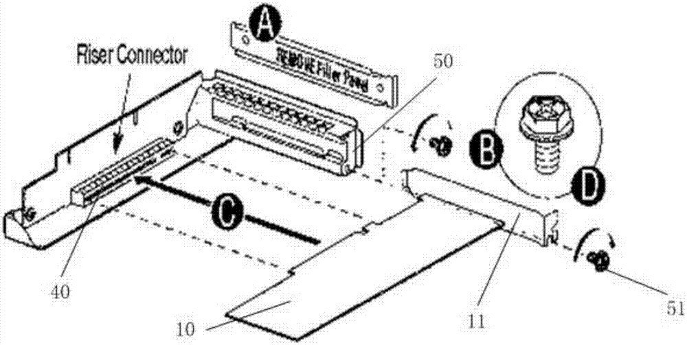
[0003] In the prior art, when a PCIE card is installed, a fixing method of the PCIE card inserted in the card slot on the adapter plate is: figure 1 A structural schematic diagram of a prior art fixing device is shown, as figure 1 As shown, after the PCIE card 10 is inserted into the card slot 40 along the direction C, the retaining piece 11 of the head of the PCIE card 10 is fixed on the fixing bracket 50 with the fixing screw 12. Requires tools to achieve screw 51 removal
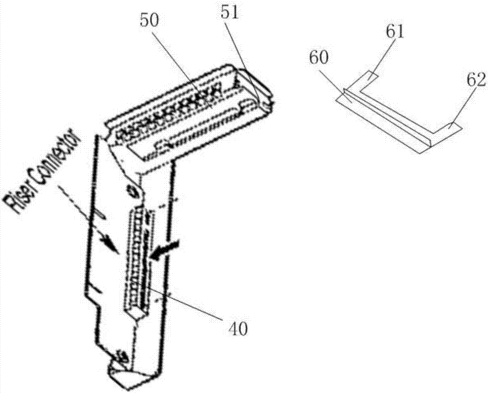
In order to facilitate the removal of the PCIE card, there is another fixing method in the prior art: figure 2 A schematic structural view of another prior art fixing device is shown, based on figure 1 After inserting the PCIE card 10 along the direction C into the card slot 40 as shown, as figure 2 As shown, the PCIE card 10 is fixed on the fixed support 50 by using the rotating bead 60, and the two ends of the rotating bead 60 are flexibly connected to the fixed support 50 through two rotating shaft fulcrums (60, 62), and the PCIE card is fixed on the PCIE support When the rotating bead blocks the head of the PCIE card, the rotating bead in this fixed structure is prone to the phenomenon that the rotating bead is easy to trip when it is subjected to vibration or even impact, especially when the rotating bead is inserted into the chassis along the expansion card. When there is an external force in the direction of the slot, it is easy to trip and cause damage to the PCIE card

Method used


Image

  • Expansion card fixing apparatus and case
  • Expansion card fixing apparatus and case
  • Expansion card fixing apparatus and case

Examples


Embodiment Construction

[0028] In order to make the object, technical solution and beneficial effects of the present invention more clear, the present invention will be further described in detail below in conjunction with the accompanying drawings and embodiments. It should be understood that the specific embodiments described here are only used to explain the present invention, not to limit the present invention.

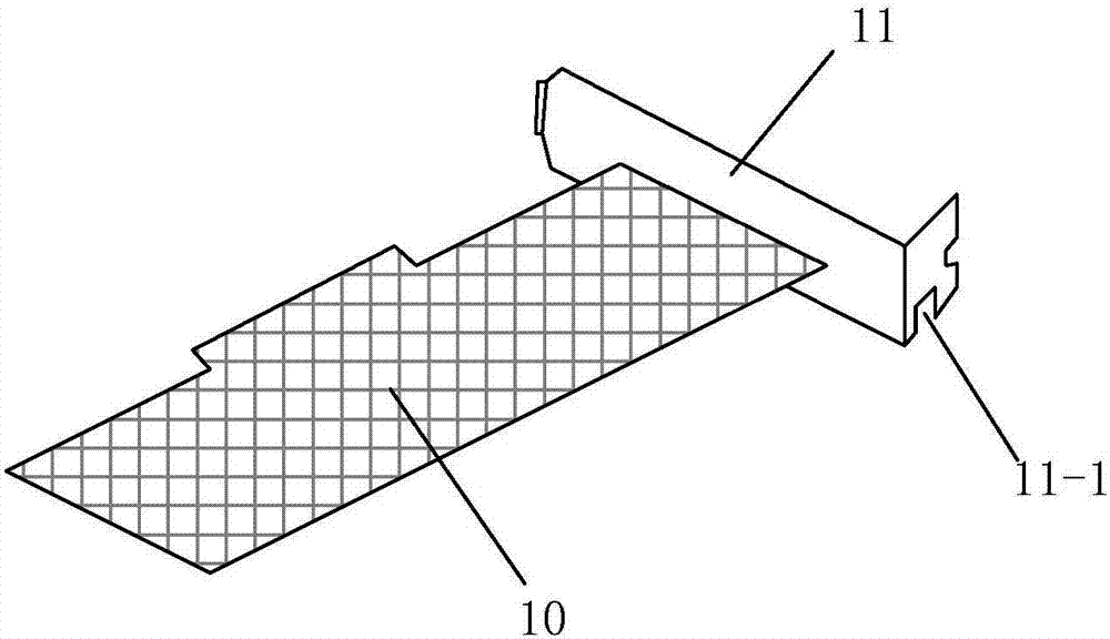
[0029] image 3 A schematic structural diagram of an expansion card provided by an embodiment of the present invention is shown. Such as image 3 As shown, the head of the expansion card 10 is connected with a blocking plate 11, and the blocking plate 11 is provided with a blocking plate groove 11-1. Wherein, when the expansion card 10 is fixed inside the chassis, one side of the expansion card 10 is inserted into the slot on the chassis, and the retainer groove 11-1 is connected with the fixing device inside the chassis to realize that the expansion card 10 is fixed inside the chassis...


PUM


Abstract

Embodiments of the invention relate to the field of product structures, in particular to an expansion card fixing apparatus and a case. The apparatus is used for realizing expansion card fixing and dismounting operations in a tool-free manner; and a limiting part is difficultly separated. The expansion card fixing apparatus comprises a bracket, the limiting part and a locking part. The bracket is fixed in the case in a direction perpendicular to an expansion card; an ejection plate of the bracket is provided with a raised part; the raised part is matched with a baffle sheet groove of the expansion card; the raised part hooks the expansion card through the baffle sheet groove; and a card slot with an opening towards the ejection plate is formed in a side surface of the limiting part and used for loading the ejection plate and the raised part and limiting the baffle sheet groove in a first direction, wherein the first direction is a direction in which the expansion card is inserted in a slot of the case. The limiting part can rotate around a first end as a rotary shaft, so that the baffle sheet groove of the expansion card is fixed and dismounted in the tool-free manner. The locking part locks the limiting part and the ejection plate of the bracket, so that the limiting part is difficultly separated.

Description

technical field [0001] The embodiment of the present invention relates to the field of product structure, and in particular to a fixing device and a chassis for an expansion card. Background technique [0002] Computers have become an indispensable electronic device in people's lives in today's society. There are various expansion cards in personal computers, mainframe computers, and server systems. Take the Peripheral Component Interconnect-Express (PCI-E) card as an example. Most of the PCI-E cards in the computer case are fixed by screws or rotating bezels. [0003] In the prior art, when a PCIE card is installed, a fixing method of the PCIE card inserted in the card slot on the adapter plate is: figure 1 A structural schematic diagram of a prior art fixing device is shown, as figure 1 As shown, after the PCIE card 10 is inserted into the card slot 40 along the direction C, the retaining piece 11 of the head of the PCIE card 10 is fixed on the fixing bracket 50 with the...

Claims


Application Information

Patent Timeline
IPC IPC(8): G06F1/18
CPCG06F1/185
Inventor 李月明周海晨
Owner XIAN YIPU COMM TECH
Learn More