
A Control Method for Improving Disturbance Suppression Ability of Tilting Mirror Control System

A control system and disturbance suppression technology, applied in general control systems, control/regulation systems, adaptive control, etc., can solve problems such as the load should not be too high, the stability control requirements cannot be met, and the disturbance suppression capability of the tilt mirror is insufficient. The effect of improving the internal loop characteristics of the system, improving the disturbance suppression capability, and improving the disturbance suppression capability

Active Publication Date: 2020-08-11
INST OF OPTICS & ELECTRONICS - CHINESE ACAD OF SCI
View PDF7 Cites 0 Cited by
  • Summary
  • Abstract
  • Description
  • Claims
  • Application Information

AI Technical Summary

Problems solved by technology

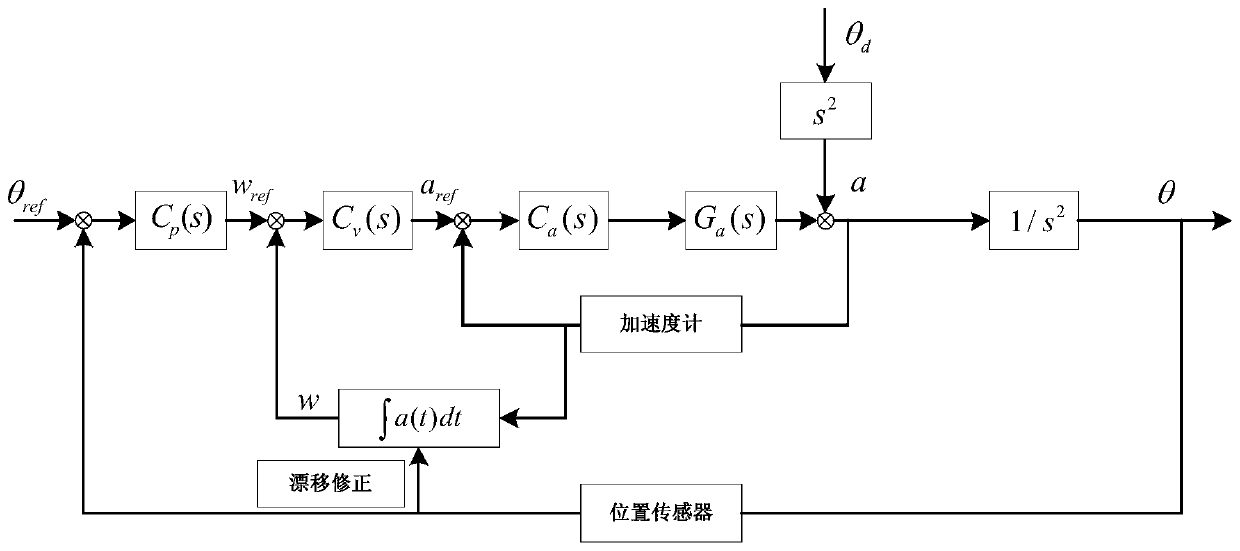
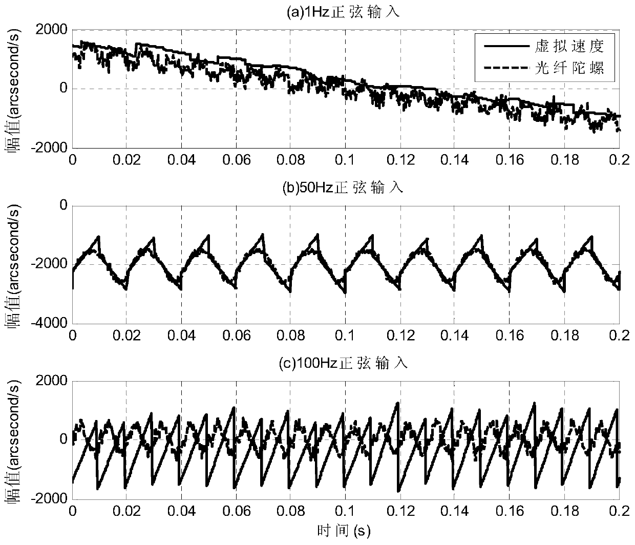
[0003] Aiming at the current requirement that the load of the tilting mirror should not be too high, the disturbance suppression ability of the tilting mirror is insufficient, and it cannot meet the demand for higher-precision stable control. The present invention proposes a control method for improving the disturbance suppression capability of the tilting mirror control system. The method The acceleration sensor signal is integrated into a virtual speed signal to simulate real motion speed information instead of using a gyro sensor

Method used


Image

  • A Control Method for Improving Disturbance Suppression Ability of Tilting Mirror Control System
  • A Control Method for Improving Disturbance Suppression Ability of Tilting Mirror Control System
  • A Control Method for Improving Disturbance Suppression Ability of Tilting Mirror Control System

Examples


Embodiment Construction

[0035] The specific implementation manners of the present invention will be described in detail below in conjunction with the accompanying drawings.

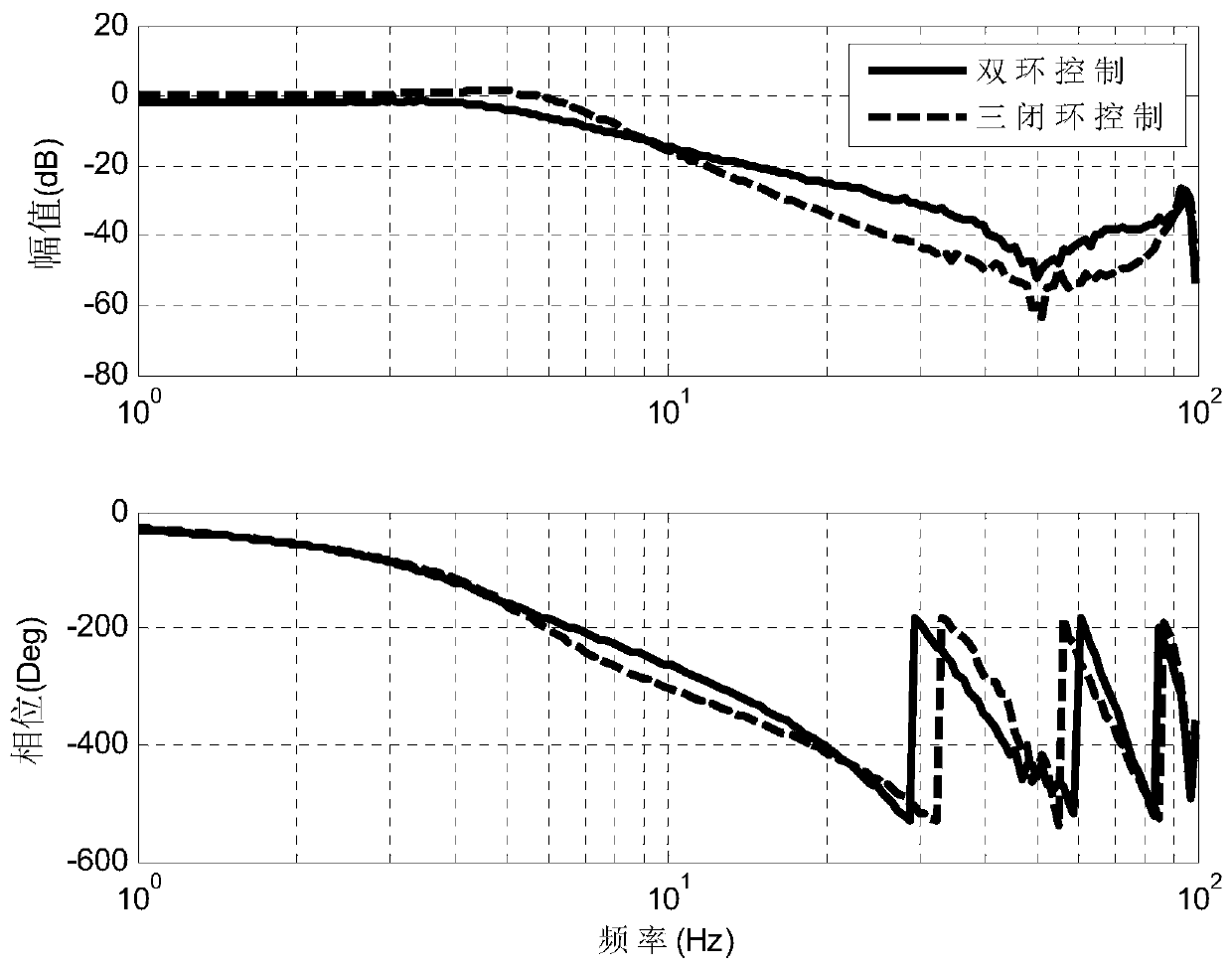
[0036] Such as figure 1 Shown is a control block diagram of a control method to improve the disturbance suppression ability of the tilting mirror control system, which includes an acceleration loop, a virtual velocity loop and a CCD position loop; on the basis of only using the acceleration sensor and the CCD position tracking sensor, three Closed-loop control, compared with the traditional method of one sensor corresponding to one closed-loop loop, can further improve the anti-interference ability of the tilting mirror while reducing the number of gyro sensors used.

[0037] The specific implementation steps of adopting described device to realize three closed-loop control methods are as follows:

[0038] Step (1): Accelerometers are installed on the two deflection axes of the tilting mirror stabilized platform to sense the an...


PUM


Abstract

The invention relates to a control system for improving the disturbance suppression capability of a tilting mirror control system. According to the method, acceleration sensor signals are integrated into virtual speed signals under the condition of only using an acceleration sensor and a CCD position sensor so as to obtain moving speed information of a tilting mirror. The acceleration sensor signals are insensitive to low-frequency motions, so that a great error exists by directly using the virtual speed signals for feedback control, and the virtual speed signals need to be corrected through introducing CCD position sensor signals. Three-closed-loop control for the acceleration, the virtual speed and the position is achieved, and thus the stability of the system is further improved under the condition that load requirements of the control system are met. The method multiplexes the acceleration sensor signals according to an integral principle, a gyroscopic sensor is replaced, and the cost is saved; and meanwhile, the control method is clear in thinking, simple in structure and easy to implement in engineering.

Description

technical field [0001] The invention belongs to the field of inertial stability control, and in particular relates to a control method for improving the disturbance suppression ability of a tilting mirror control system, which is mainly used for reducing system load and improving the tracking performance of a motion platform photoelectric tracking device. Background technique [0002] In photoelectric tracking equipment, as an important part of the beam stabilization control system, the tilting mirror has been widely used in astronomy, aerospace and other scientific research fields. However, the closed-loop performance of the tilting mirror is severely limited by the low sampling rate and mechanical resonance of the CCD. Therefore, a multi-closed-loop approach is often used to improve the performance of the tilting mirror control system. However, the tilting mirror control system has strict requirements on the system load, resulting in insufficient assembly conditions to add...

Claims


Application Information

Patent Timeline
Patent Type & Authority Patents(China)
IPC IPC(8): G05B13/04
CPCG05B13/042
Inventor 任维邓超毛耀张超李志俊
Owner INST OF OPTICS & ELECTRONICS - CHINESE ACAD OF SCI
Learn More