
Experiment device and method for measuring turbulent friction resistance of flat plate

A technology for measuring flat plates and experimental devices, which can be used in measuring devices, aerodynamic tests, and testing of machine/structural components. Large ground area and other problems, to achieve the effect of stable experimental smoke flow, reliable design principle, and easy operation

Active Publication Date: 2017-12-22
ZHEJIANG UNIV
View PDF8 Cites 14 Cited by
  • Summary
  • Abstract
  • Description
  • Claims
  • Application Information

AI Technical Summary

Problems solved by technology

[0003] At present, the experimental devices and methods for the measurement of flat plate flow resistance in the prior art usually use traditional circulating water tanks or towed pool devices, such as the application number: 200510132080.7, which is named "a flat plate wall fluid friction resistance based on open circulation Measuring device" and CN 105387993 A, titled "a flat surface fluid resistance performance test device" and CN 104634538 A, titled "a kind of experimental device for measuring flat plate flow resistance"; traditional circulating water tank or drag pool experimental device, There are problems such as complex structure, large footprint, difficult to accurately control the flow field in the experimental section, and difficult to accurately capture the velocity distribution inside the flat turbulent boundary layer. However, there is no research on the frictional resistance measurement of the flat turbulent boundary layer in the air environment. Related technical mentions

Method used


Image

  • Experiment device and method for measuring turbulent friction resistance of flat plate
  • Experiment device and method for measuring turbulent friction resistance of flat plate

Examples


Embodiment Construction

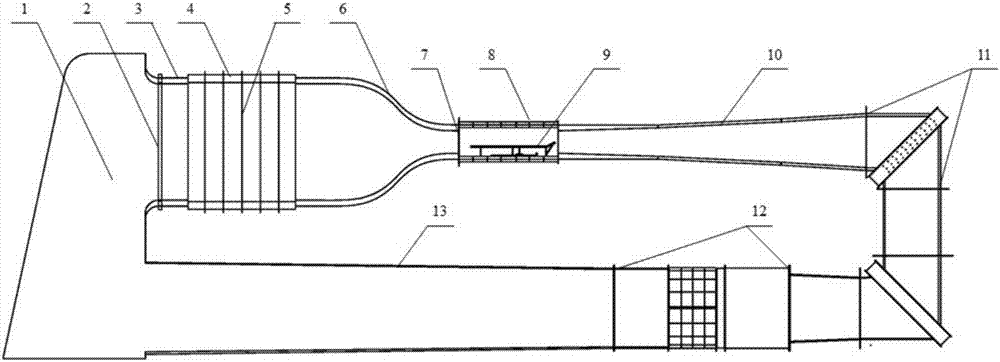
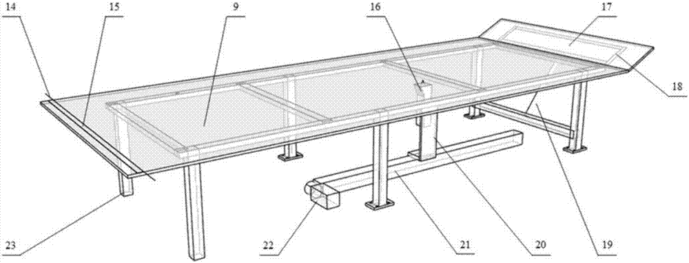
[0017] Attached below figure 1 and figure 2 And embodiment the present invention is described in more detail.

[0018] According to the experimental device for measuring flat turbulent frictional resistance provided by the invention, such as figure 1 , figure 2 As shown, it includes a smoke collection chamber 1, and an air channel formed by sequential connection of a gas collection section 3, a stable section 4, a contraction section 6, an experimental section 8, a diffusion section 10, a corner section 11, a power section 12, and an outlet section 13 , the smoke collection chamber is connected to the gas collection section and the outlet section to form a complete air circulation system, and the air flow direction is from the gas collection section to the outlet section through the entire air channel.

[0019] A smoke generator and a smoke diffusion fan are arranged in the smoke collection chamber 1, and a noise-absorbing net 2 is arranged vertically to the air flow dire...


PUM


Abstract

The invention provides an experiment device and method for measuring the turbulent friction resistance of a flat plate, and belongs to the technical field of aerodynamics testing. The experiment device comprises a smoke collecting chamber, an air channel, a test flat plate, a velocity collector, a guide rail, a sliding block and a stepper motor, and is characterized in that the air channel is formed by sequentially connecting an air collecting section, a stabilizing section, a contracting section, an experiment section, a diffusing section, a corner section, a power section and an outlet section, the smoke collecting chamber enables the air collecting section and the outlet section of the air channel to be communicated so as to form a set of complete air circulation system, the test flat plate is fixed at the center of the experiment section, the guide rail is arranged on the wall of the experiment section below the test flat plate, the guide rail is set in a mode of being parallel to the air flowing direction, and a laser probe of the velocity collector is fixed on the sliding block on the guide rail. The experiment device is simple in structure and simple and convenient to operate, directly measures an average velocity profile of the flat plate at different flowing direction positions, solves the friction velocity through fitting and calculates the wall friction stress and local resistance coefficient of a turbulent boundary layer of the flat plate.

Description

technical field [0001] The invention relates to an experimental device and method for measuring flat turbulent frictional resistance, which is used for measuring flat wall turbulent boundary layer frictional resistance at a flow velocity of 5-30m / s, and belongs to the technical field of aerodynamic testing. Background technique [0002] Aircraft flying in the atmosphere, the main energy consumption is used to overcome the flight resistance, and the drag problem related to the aircraft, two aspects must be considered: most of the flow in aviation applications is high Reynolds number, and the flow shows turbulent flow characteristics; the surface friction of the aircraft Resistance is the main component of total resistance, and to reduce total resistance must be achieved by reducing frictional resistance. Therefore, the resistance analysis of aircraft components is of great significance for saving energy and improving work efficiency. Since the frictional resistance accounts ...

Claims


Application Information

Patent Timeline
IPC IPC(8): G01M9/06
CPCG01M9/06
Inventor 郑耀邹建锋叶志贤楼韫闻童小康闾曾怡俞天纬陈烨斯张永兴
Owner ZHEJIANG UNIV
Learn More