Storage tank

A storage tank and tank body technology is applied in the field of sealing devices for storage tanks, which can solve problems such as safety accidents and low reliability, and achieve the effects of reliable sealing, low cost and reliable sealing.

Pending Publication Date: 2017-12-22
浙江美丽健乳业有限公司
View PDF0 Cites 0 Cited by
  • Summary
  • Abstract
  • Description
  • Claims
  • Application Information

AI Technical Summary

Problems solved by technology

In the prior art, the tank pressure control is manually operated, which has low reliability and is prone to safety accidents

Method used


Image

  • Storage tank
  • Storage tank

Examples


Embodiment Construction

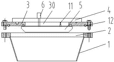
[0021] The invention as Figure 1-2 Shown, comprise the tank body 1 of top opening 2, the top of described tank body is provided with flange plate 3, and described flange plate has middle hole 30, and the aperture of described middle hole is less than the caliber of tank body top opening;

[0022] The top surface of the flange is provided with an upper cover plate 4, and the bottom surface is provided with a lower cover plate 5. The center lines of the upper cover plate, the middle hole and the lower cover plate are consistent, and the upper cover plate and the lower cover plate are respectively For closing the middle hole;

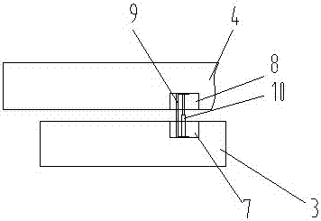
[0023] The top surface of the flange 3 is provided with an annular hole 1 7, and the upper cover plate 4 is provided with an annular hole 2 8, the annular hole 1 and the annular hole 2 are oppositely arranged, and the annular hole 1 and the annular hole 1 are arranged oppositely. The second is provided with an annular filter-9;

[0024] The section of t...


PUM


Abstract

The invention provides a storage tank which is simple in structure and capable of improving reliability and safety. The storage tank comprises a tank body with the top being opened. A flange plate is arranged at the top of the tank body. The flange plate is provided with a middle hole. The hole diameter of the middle hole is smaller than the opening diameter of a top opening of the tank body. An upper cover plate is arranged on the top face of the flange plate, and a lower cover plate is arranged on the bottom face of the flange plate. The center lines of the upper cover plate, the middle hole and the lower cover plate are consistent. The upper cover plate and the lower cover plate are used for closing the middle hole. A first electric drive pusher is arranged on the top face of the upper cover plate. A push rod of the first electric drive pusher penetrates through the upper cover plate and is further connected with the lower cover plate. A second electric drive pusher is arranged between the upper cover plate and the lower cover plate. A push rod of the second electric drive pusher is connected with the upper cover plate. The storage tank can be processed conveniently and is low in cost.

Description

technical field [0001] The invention relates to a tank body, in particular to a sealing device for a storage tank. Background technique [0002] The tank, as a storage container for gas or liquid, often receives and discharges a large amount of materials in daily use. In this way, it is necessary to control the sealing and pressure of the tank. The material is damaged, reducing the quality of the product. The pressure in the tank is controlled to prevent the tank from bursting when the pressure is too high or the tank is deformed when the pressure is too low. In some special processing fields, while controlling the pressure of the tank, it is also necessary to ensure that the tank is discharged to avoid bringing out materials. In the prior art, the tank pressure control is manually operated, which has low reliability and is prone to safety accidents. Contents of the invention [0003] Aiming at the above problems, the present invention provides a storage tank with simple...

Claims


Application Information

Patent Timeline
IPC IPC(8): F16J13/12F16J13/24F16J12/00F17C13/02F17C13/06F17C13/12
CPCF16J12/00F16J13/12F16J13/24F17C13/025F17C13/06F17C13/12F17C2205/0311F17C2250/043F17C2260/04
Inventor 王昆鹏宗保林袁同泉
Owner 浙江美丽健乳业有限公司
Why Eureka
Try Eureka