Weak pressure, sudden drop and sudden expansion jet stilling pool energy dissipation system in the cave

A stilling pool and sudden drop technology, which is applied in sea area engineering, construction, barrage/weir, etc., can solve the problems of large amount of engineering excavation, increased engineering difficulty, and poor economic efficiency, so as to ensure safe operation and reduce engineering costs. The effect of increased excavation volume and structural stability

Active Publication Date: 2019-08-20
SICHUAN UNIV
View PDF4 Cites 0 Cited by
  • Summary
  • Abstract
  • Description
  • Claims
  • Application Information

AI Technical Summary

Problems solved by technology

Existing energy dissipators in non-pressure tunnels mainly include orifice plate energy dissipators, swirling flow energy dissipaters, cone valve energy dissipators and non-pressure stilling pool energy dissipators in tunnels. The structure of the pressure stilling basin is similar to that of the conventional underflow stilling basin, that is, the stilling basin in the tunnel is underflow energy dissipation under the condition of no pressure, and the height of the stilling basin d=(1.75-1.90)X (X is the height of the upstream tunnel ), which requires the excavation of a relatively large stilling pool elevation (cave top elevation) to prevent the alternating open and full flow in the pool to meet the pressure-free requirements, and reduce the height of the apron or set the stilling sill at the end of the stilling pool Increase the depth of the tail water and form a hydraulic jump in the stilling basin to achieve the purpose of energy dissipation. Therefore, the engineering excavation volume is large, the economy is poor, and the engineering difficulty will increase with the increase of the excavation height of the stilling basin

Method used


Image

  • Weak pressure, sudden drop and sudden expansion jet stilling pool energy dissipation system in the cave
  • Weak pressure, sudden drop and sudden expansion jet stilling pool energy dissipation system in the cave
  • Weak pressure, sudden drop and sudden expansion jet stilling pool energy dissipation system in the cave

Examples


Embodiment 1

[0029] The engineering overview of embodiment 1 and comparative example 1 is as follows:

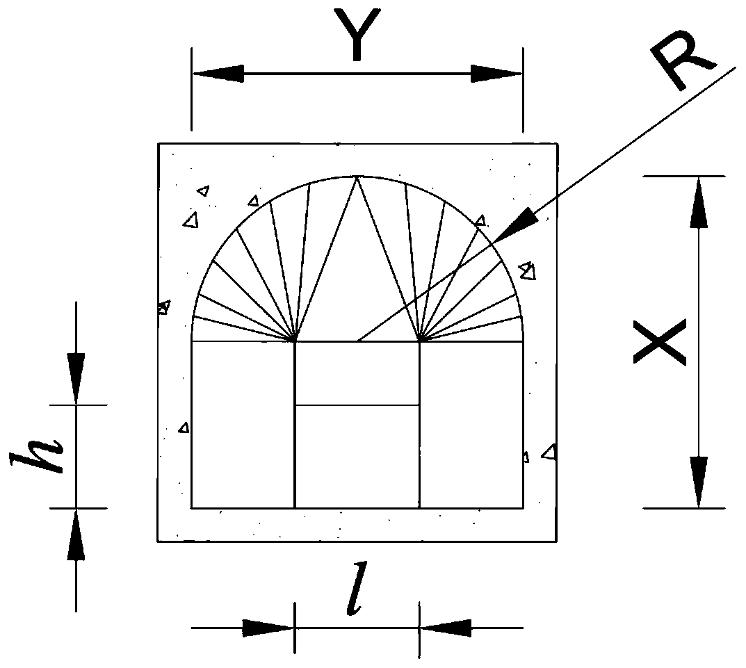
[0030] The flow tunnel is in the shape of a city gate, with a height of X = 16m, a width of Y = 16m, and a flood discharge of 1200m 3 / s.

[0031] Aiming at the above projects, two energy dissipation systems of Example 1 and Comparative Example 1 were used to carry out hydraulic model tests.

[0032] Example 1

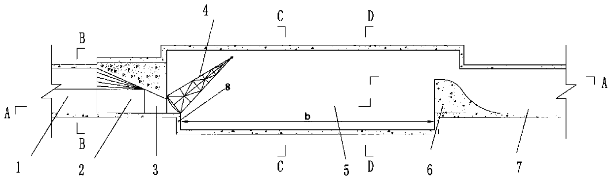
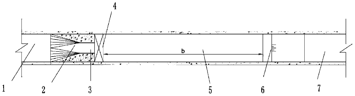
[0033] In this embodiment, the energy dissipation system of the jet stilling pool with weak pressure, sudden drop and sudden expansion in the cave is a single jet hole structure, and the structure is as follows Figure 1-5 As shown, from upstream to downstream, there are the jet hole section connected with the upstream tunnel section 1, the drop sill 8 arranged at the outlet of the jet hole section, the low-pressure stilling pool 5 connected with the drop sill, and the tail of the low-pressure stilling pool connected with The tail sill 6 of the downstream tunnel section 7 is p...

Embodiment 2

[0042] The engineering overview of embodiment 2 and comparative example 2 is as follows:

[0043] The flow tunnel is in the shape of a city gate, with a height of X = 19m, a width of Y = 17m, and a flood discharge of 1,800m 3 / s.

[0044] Aiming at the above projects, two energy dissipation systems of Example 2 and Comparative Example 2 were used to carry out hydraulic model tests.

[0045] Example 2

[0046] The energy dissipation system of the jet stilling pool with weak pressure, sudden drop and sudden expansion in the cave described in this embodiment is in the form of double jet holes, and the structure is as follows Figure 6-10 As shown, the two jet holes are arranged side by side with a distance of 5m. The shape and size of the two jet holes are the same. The top of the low-pressure stilling tank 5 is lined with reinforced concrete. All the other structures are with embodiment 1.

[0047] The dimensions of each part of the structure are as follows: the width of the...


PUM


Abstract

An in-tunnel weak pressure sudden dropping and sudden expansion type jet flow stilling pool energy dissipation system is composed of a jet flow hole section connected with an upstream tunnel section, a drop sill arranged at an outlet of the jet flow hole section, a low-pressure stilling pool connected with the drop sill, and a tail sill connected with the tail of the low-pressure stilling pool and a downstream tunnel section from the upstream section to the downstream section in sequence. A gate matched with jet flow hole outlets is arranged at the outlet of the jet flow hole section and located above the drop sill. The jet flow hole section is provided with at least one jet flow hole, and the jet flow holes are formed by connecting a contraction type transition section with a pressing slop section in the water flow direction. In the formula d=(1.3-1.5)X, wherein d is the height of the low-pressure stilling pool, and X is the height of an upstream tunnel. Through the in-tunnel weak pressure sudden dropping and sudden expansion type jet flow stilling pool energy dissipation system, the energy dissipation effect can be ensured, cavitation and cavitation erosion as well as bottom plate scouring can be avoided, meanwhile, the engineering excavated volume is decreased, and the safety and economical efficiency of engineering are improved.

Description

technical field [0001] The invention belongs to the technical field of energy dissipation in water conservancy and hydropower projects, and relates to an energy dissipation system of a stilling pool suitable for energy dissipation in hydraulic tunnels. Background technique [0002] In the construction of water conservancy and hydropower stations, in order to ensure the safety of water conservancy projects in operation, a series of flood discharge measures need to be adopted, and tunnels are one of the traditional and commonly used discharge structures. In order to ensure the safety of the tunnel during flow, it is usually necessary to ensure that the hydraulic indicators such as pressure and flow velocity in the tunnel are within the safe range, which requires the use of energy dissipation in the tunnel. Existing energy dissipators in non-pressure tunnels mainly include orifice plate energy dissipators, swirling flow energy dissipaters, cone valve energy dissipators and non-...

Claims


Application Information

Patent Timeline
Patent Type & Authority Patents(China)
IPC IPC(8): E02B8/06
Inventor 张建民许唯临彭勇刘善均邓军田忠汪凯迪张法星周茂林
Owner SICHUAN UNIV
Why Eureka
Try Eureka